
The Flight manual for my Mockup of the L-410 for Stormworks. Includes Normal Operations, Abnormal operations, Supplementary procedures, and Operational Engineering bulletins. Complete with Checklists and Tables!
Welcome
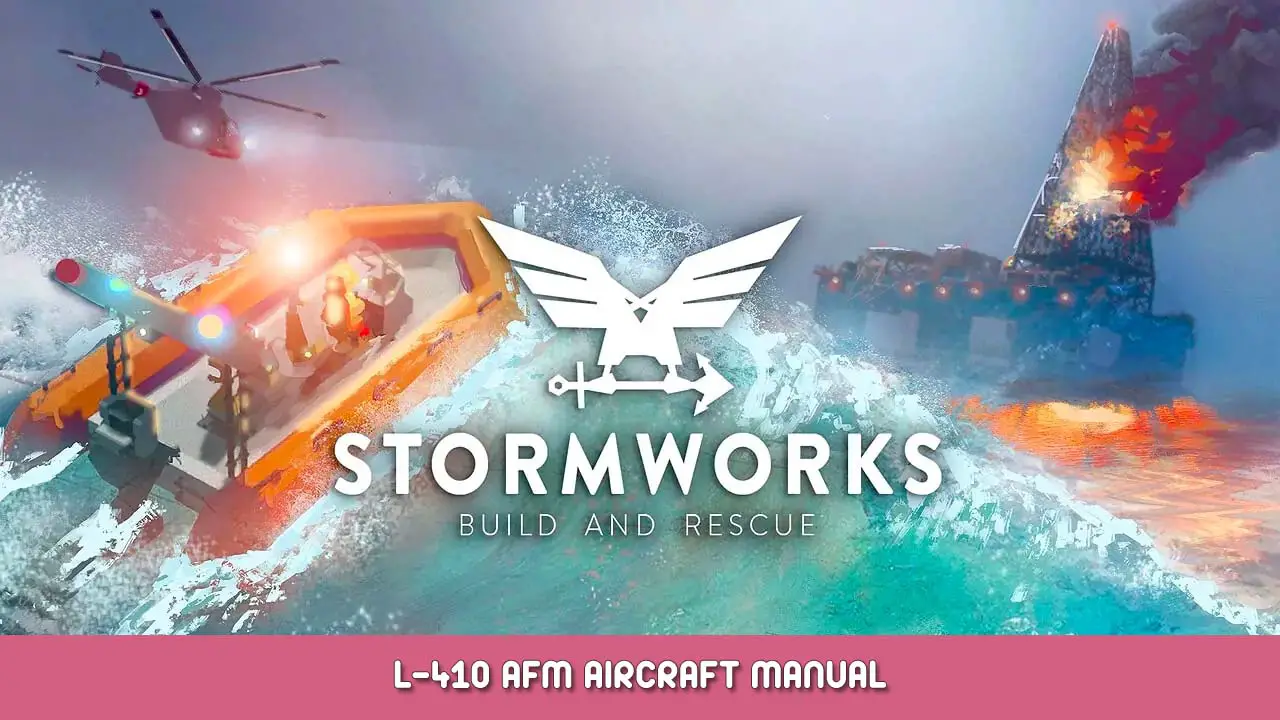
Welcome to my version of the L-410 for Stormworks, which can be found here.
I’m a bit of a geek and have decided to make a mini manual for this aircraft. It is split into sections of varying information. This is my first proper release to the workshop so I hope you enjoy.
Do feed back anything odd or anything weird in the comments below (Other than the fact I have written a manual for this thing) but check the OEB section to see if its already been reported or if its known about.
Happy flying folks.
Change and revision log
General Description and Limitations
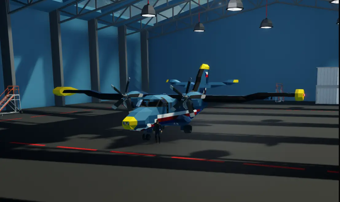
The L-410 is a twin turbo prop, conventionally controlled aircraft (Or atleast this version is). It is equipped with a tricycle gear configuration.
The aircraft costs $25,276 to spawn.
L-410a
Length: 14.5 meters
Wingspan: 20 meters
Height: 5.75meters
25000ft
Zero Fuel Weight:4276lg
Crew: 3
Passengers: 10
This aircraft is single pilot approved.
Equipped with two turbo prop “Basic” Engines developed (crudely) by me
Max RPM:2500
L-410a: Jet A1 ONLY
Max Capacity: 7093 Units
The speeds listed below were all tested in still air. It must be noted that these speeds will change based on wind conditions.
Recommended cruise Speed: 125kts (Initially around 75% throttle)
VNE: 250kts
VNO:205kts
VFE: Approved all the way up to VNE
VR: 80kts
VMC: 90kts
VS1: 66kts
VS0: 60kts
VNE:Velocity Never Exceed -This is the maximum speed of the aircraft before structural damage will occur.
VNO: Velocity Normal Operations – This is the speed of normal operations. Anything above this must be in still air with no turbulence and with caution exercised.
VFE: Velocity Flap Extension – This is the max speed the flaps can be operated without damaging them. Luckily this is a video a game and damage will not occur.
VR: Velocity Rotate – The speed you apply a nose up input to “Rotate” The aircraft up off the ground, neat huh?
VMC: Velocity Minimum control – This is the speed that in flight: If one engine is failed, is the minimum speed lateral control can be maintained. Anything below this will result in a loss of control.
VS0 :Velocity of Stall with configuration. – This is the stall speed of the aircraft with Flaps full and the landing gear down
VS1: Velocity of stall in a clean configuration. – This is the stall speed of the aircraft in the clean configuration.
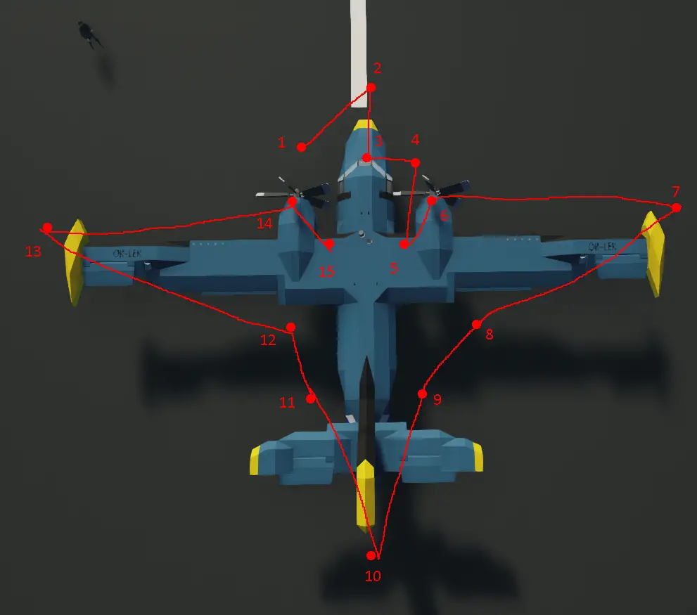
Cockpit layout
This Chapter will include the basic layout of the cockpit and overhead panel for Pilot Familiarity.

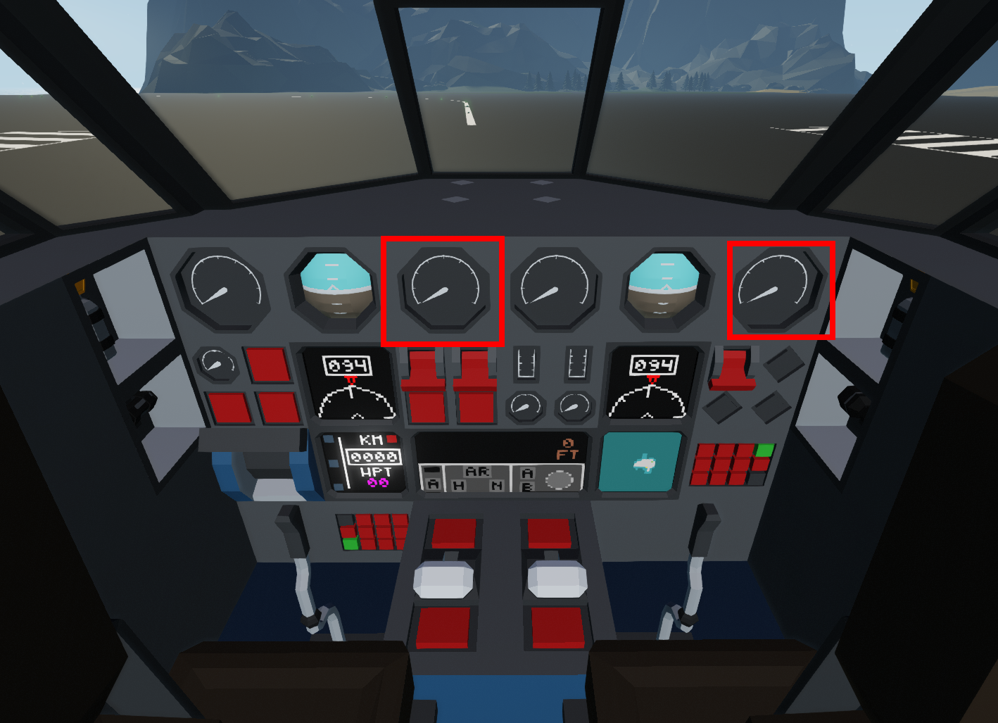
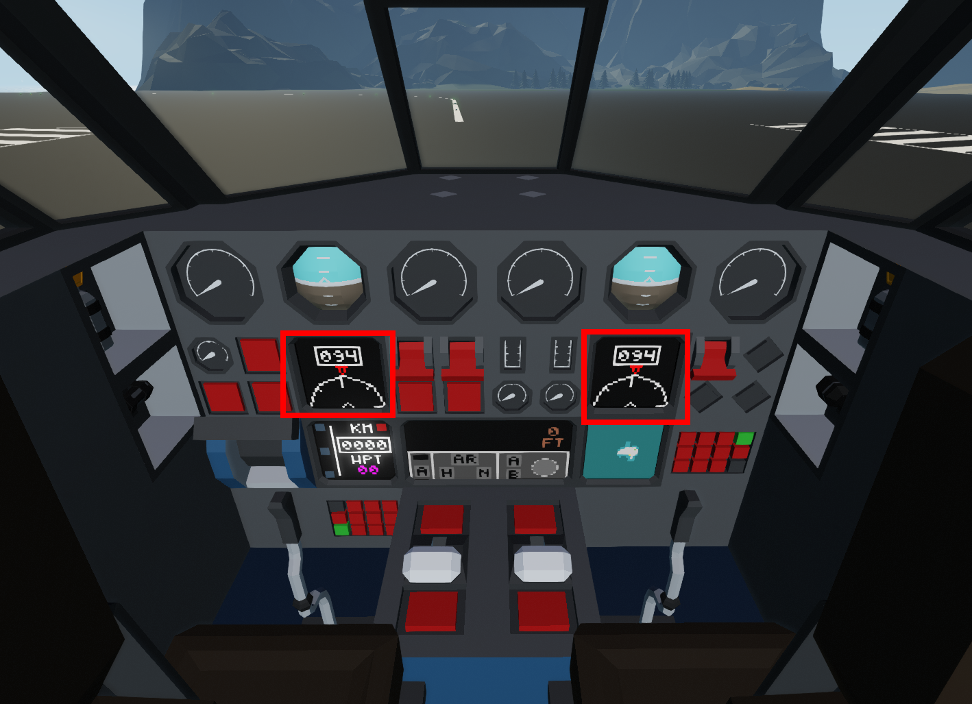
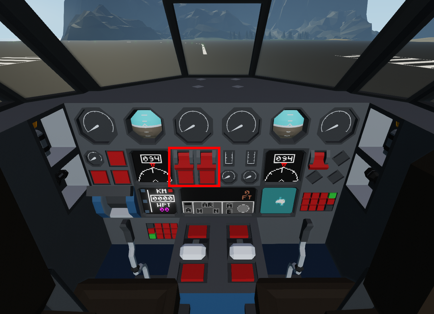
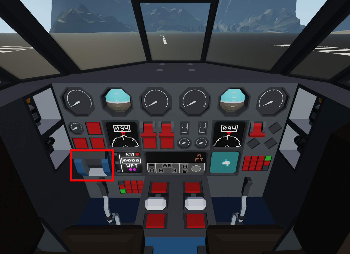
Each side has a T configuration for flight information. Engine Instruments are centralised along with the autopilot, Flaps and Gears are on the extremities.
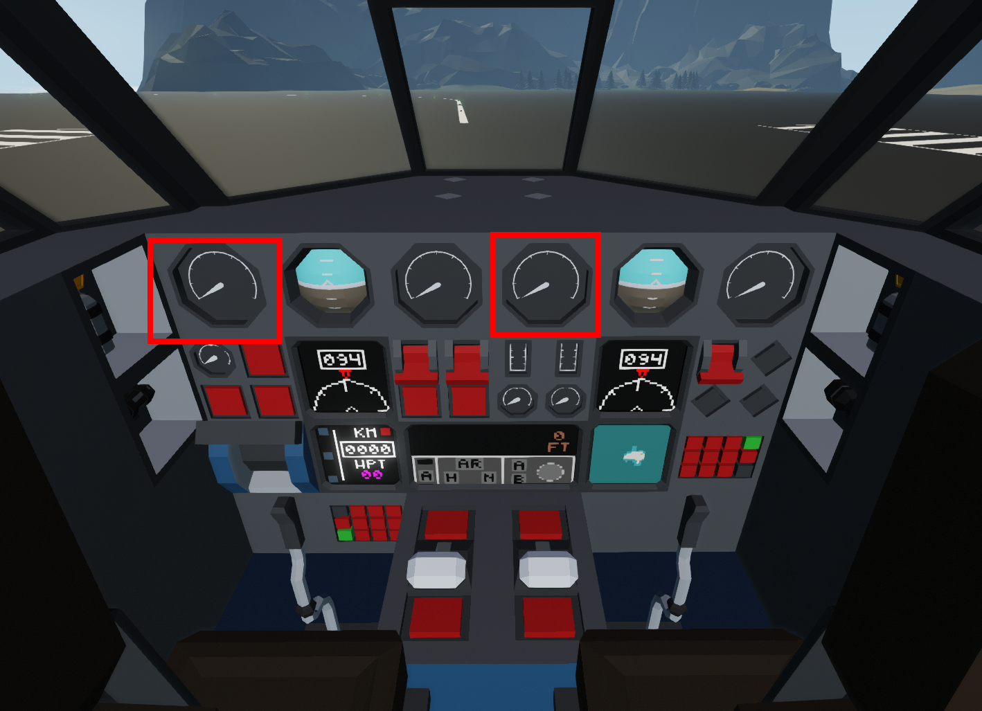
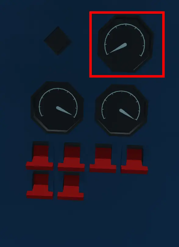
Displays the speed indicated in Knots

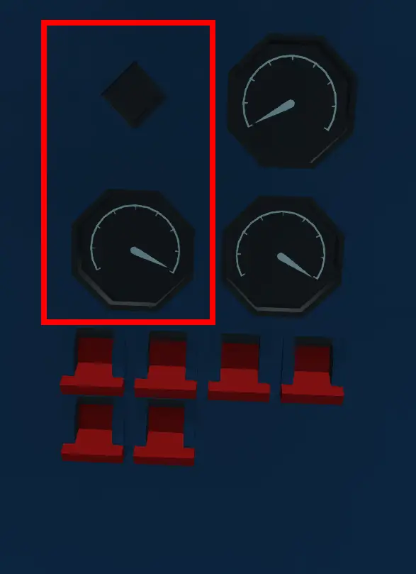
Displays Bank and Pitch angles of the aircraft
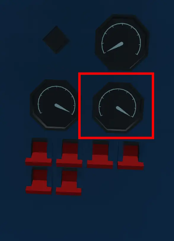
Displays the altitude indicated in feet

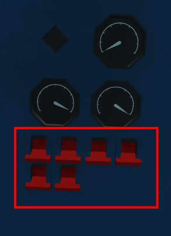
Dial displays the Flap position (0, 0.2 or 0.4) Buttons include 0, TO and LDG.
Displays the current heading of the aircraft
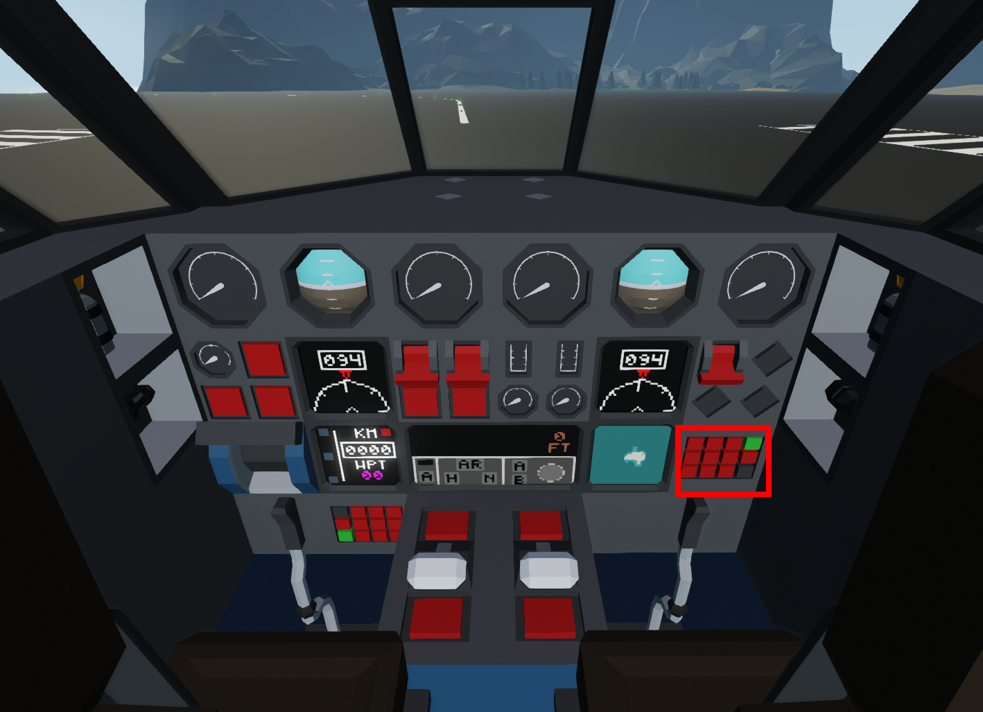
The flip switches turn the PIDs on. The starter starts the compressors of the engines.

RPM displayed on the gauge, temperature is displayed on the dial
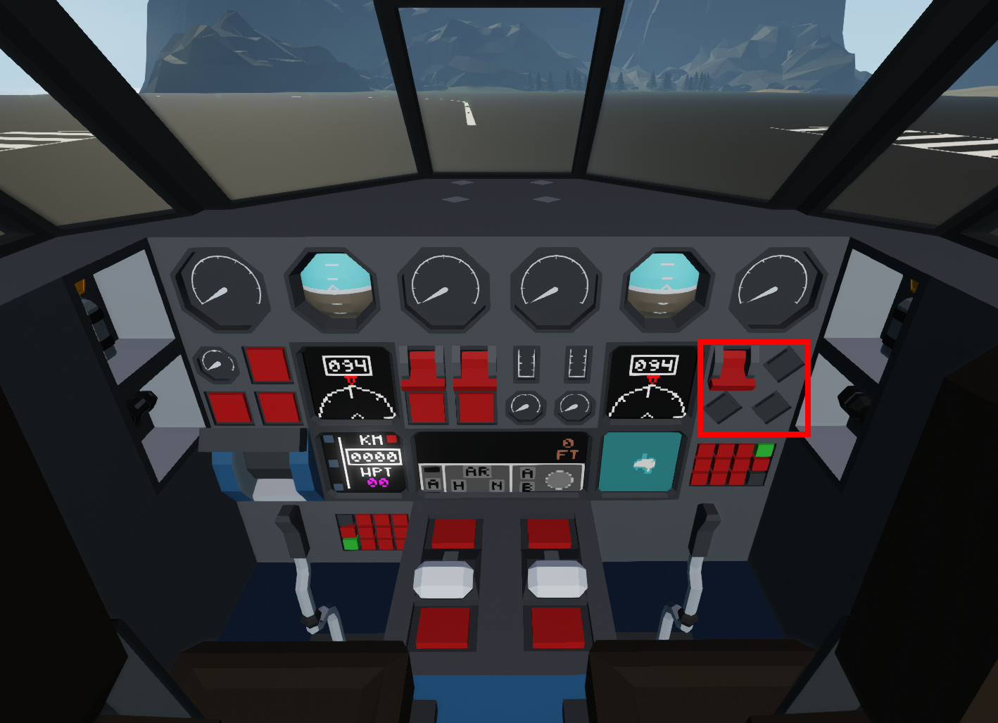
Flip switch indicates selected position of gear (Up, Gear Up, Down, Gear Down) Red indicators display if the gear is not in the selected position.
Disconnects the battery from the avionics of the aircraft.

See the KAP-140 guide for more.
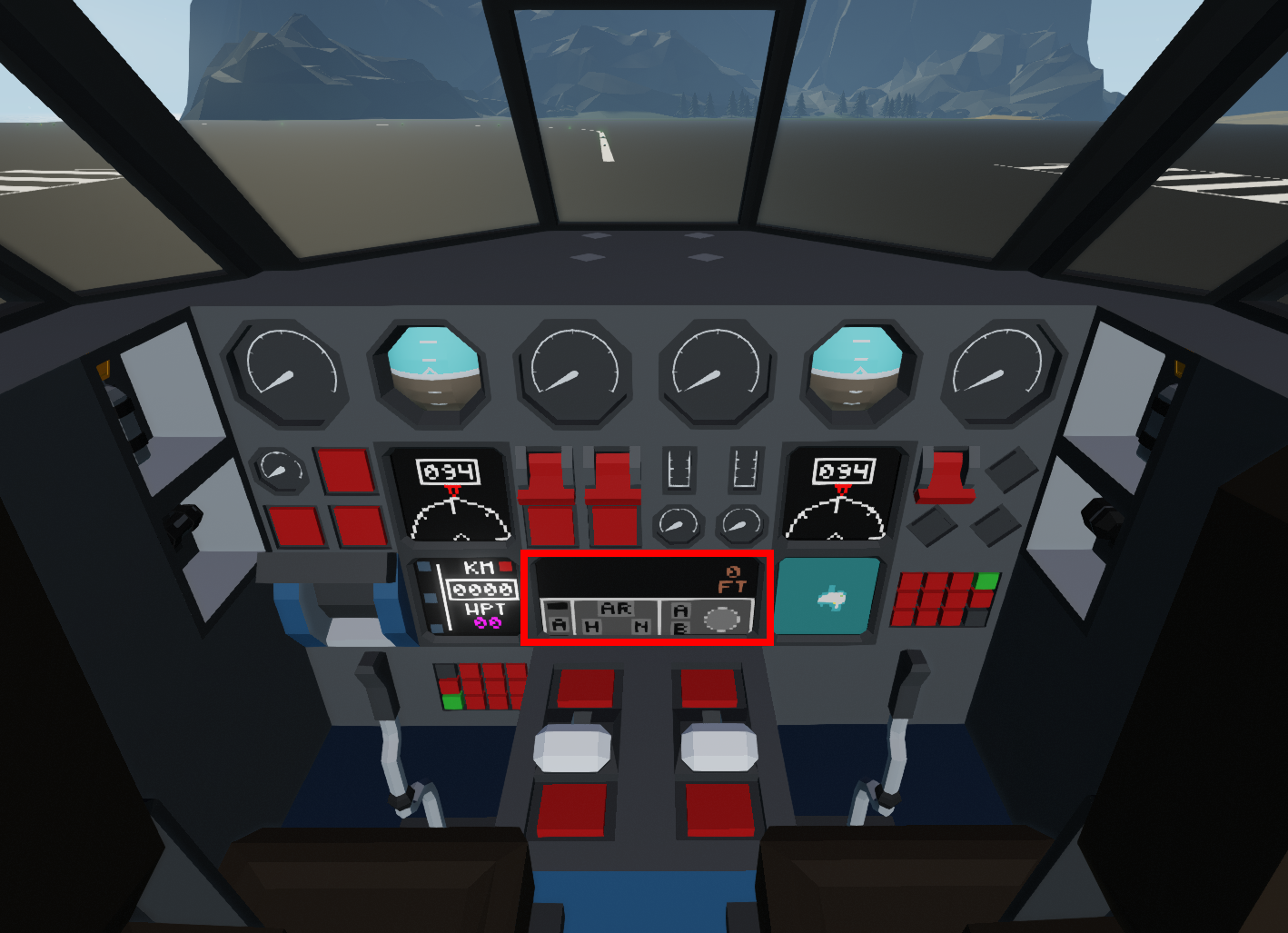
See the KAP-140 guide for more.
Used to key in the frequency for the radio.

Controls the commanded thrust for the engines.

The overhead panel is split into the lighting segment, Electric segment and Fuel segment
Lights are controlled by flip switches, all lights labelled
Battery voltage is displayed as a percentage. External power will only display if a constant ON signal is passed.
Displays the total units of fuel onboard
Provides a rough estimate of your range in kilometres based on the current fuel burn of the aircraft at the current speed. This can be in accurate, so use with care.
Normal Operations: Standard calls and Angle Limits
1)
AVIATE, NAVIGATE, COMMUNICATE.This is a fundamental thing to have. Your priority is to fly the aircraft safely first and foremost, ensure the energy state and parameters are within what could be classed as normal.
Second is Navigation, if you are not immediately about to crash into something ahead of you, are you going to in future? Where are you in relation to other airfields?
Lastly Communicate: Once you are flying nicely, navigating somewhere safe and sensible then you can communicate, inform ATC.
Remain vigilant and drilled with this and it will help assist your flying.
2)
IF THE AUTOMATICS ARE BEHAVING WEIRDLY, DISCONNECT THEMUsing the same fundamental above, if the plane behaves unexpectedly, then continue to Aviate Navigate and Communicate, this may involve dropping the autopilot out to maintain directional control.
The energy state of the aircraft needs to be constantly monitored. If flying with a Pilot Monitoring (PM) It is there duty to call anything that goes out of limits. Similarly its the Pilot flying (PF) responsibility to call any Autopilot mode changes and anything they are setting so the Pilot Monitoring is in the loop of the situation.
This could be done with calls such as:
“Engaging Alt mode”, “Engaging Nav mode”, “Disengaging Autopilot”, “Targeting __ speed”
PITCH– If the pitch is below 10 degrees or above 45 degrees
BANK ANGLE– If the bank angle is greater than 45 degrees
SPEED– If the speed is 10kts faster than the target speed or 5 kts slower than the target speed.
Normal Operations: Flows and Standard Operation
This chapter covers the flows and standard Operations for this aircraft. The checklists are in the next chapter. It is important to be comfortable with the cockpit layout before operation.
- Battery: Check Above 50%
- If lower than 50%, Consult charging Cycle Supplementary Procedure.
- Do not perform Engine start with voltage below 50%
- Fuel: Check fuel level
- Engine Masters: Check off
- Thrust Levers: Idle
- Gear: Check UP
- Flaps: Check UP
- Park Brake: Check ON (Assumed on if first spawn)
- Battery Master: ON
- Navigation Lights: ON
- Walk around: PERFORM
Stormworks is of course a game, this check doesn’t need to be performed really but here have some fun with doing it if you want a little immersion
- Left side cockpit, no damage or signs of fluid leak
- Nose Lights: Check Clear
- Nose gear and bay: Check clear, ELT indication OFF and External Power state

- Right side of aircraft, No damage or signs of fluid leak
- Landing lights and main gear, clear of damage and obstruction
- Right engine, no leaks or damage, prop area clear
- Right wing leading edge and nav light: No damage and lights operational
- Right wing trailing edge, check flaps in selected position and aileron neutral
- Right side empennage and stabilisers: No damage
- Rear Position Lights: Confirm working
Complete 11 to 15 the same as the right hand side just in reverse.
You must check that the aircraft has the following:
- 1 Fire extinguisher by the Cabin crew station
- 1 Medipack by the Cabin Crew station
- 1 Oxygen mask by each pilot seat
- 1 Torch by each pilot seat
Additionally, the aircraft must be clear of any suspicious items.
- Flight Computer: Program
- Briefing: Complete
- Clearance: Obtain
- External Power: Check disconnected (If Required)
Once Cleared to start:
- Beacon: ON
- Propeller Area: Check Clear of Obstruction
- Before Start Checklist: Perform
Once the checklist is completed and a signal has been received from ground crew the engines may be started in accordance with the following Procedure:
- Engine Master 1(2): ON
- Engine Starter: Hold until 60RPM
- Once engine is started, complete procedure for the other engine.
- Once both engines started
- Flaps: Set to TO or LDG
- Thrust Levers: Check Idle
- After Start Checklist: Perform
Once taxi clearance has been received
- Taxi Light: ON
- Parking Brake: OFF
- Thrust Levers: Max 40%
- Once above 3kts
- Brake Check: Perform
- Flight Control Check: Perform
When cleared to line up or take off:
- Strobes: ON
- Landing Lights: ON
- Check approach path and runway are clear
- Autopilot (If Required): Nav/HDG and AP Engaged
- Line up Checklist: Perform
When cleared for take off:
- Thrust Levers: Smoothly apply to 100%
- Directional Control: Maintain Centreline
- At 80kts: Gently Pitch up
- Once Aircraft is climbing away safely and Positive climb called
- Gear: UP
- Once above 100ft above the airfield:
- Auto Pilot Altitude Mode: As Required
- Once above 400ft
- Flaps: UP
- Landing and Taxi Lights: OFF
- Check Landing gear Up
During the Climb the Thrust may be adjusted appropriately.
It is recommended to do this once past 2000ft to ensure terrain clearance can be maintained.
- Cruise Throttle: Set
- It is recommended to target a speed, the lighter you become the faster you will go
- IF INSTALLED:
- Basic range calculator: Check Range is 20km greater than distance to go.
- NOTE: Use with caution, predictions can be inaccurate at times.
- IF NOT INSTALLED
- Target Speed: 120kts
- This will ensure you can atleast make it around 130kms or so if fully loaded with fuel.
- Approach Briefing: Perform
- Cabin: Secure
- Descend when ready or when cleared
- Ensure it is appropriate given terrain and the conditions
- Configure the aircraft in Take Off flaps just prior to turn onto final approach track
- Approaching final leg segment
- Ldg Mode: As Required
- Speed: VREF+10
- Prior to 1000ft
- Flaps: LDG
- Gear: DOWN
- Landing and Taxi Light: ON
- Ensure appropriate Lateral and Vertical guidance
- Landing Checklist: Perform
- At 500ft
- Speed: Maintain VREF+10 (Without Wind Correction)
- If Speed Unstable or vertical/lateral guidance lost
- Go around: Perform
- At 200ft:
- Autopilot: Disconnect if visual
- If not visual: Perform Go around
- Go Around: Announce
- Thrust Levers: 100%
- Pitch: 10-15 degrees or as required
- Flaps: Select one stage up (LDG->TO. TO->UP)
- Climb: Ensure Positive and announce
- Gear: UP
- Once above 400ft
- Flaps: UP
NOTE: Once stabilised review why you went around, check your available fuel and options
A Diversion or One more attempt can be given.
It is standard with this aircraft to only attempt two approaches unless safety is impacted
This is a go around at a very low level. Tail strike risks are higher therefore below 30ft a different procedure should initially be applied.
- Thrust Levers: 100%
- Pitch: Select a gentle climbing attitude
- Flaps: MAINTAIN
- Gear: MAINTAIN
- Once above 50ft
- Go around: Perform
- Brake: As appropriate
- Once speed is below 15kts
- Taxi off runway via taxi way
- Landing Lights: OFF
- Strobes: OFF
- Flaps: UP
Ensure your speed is between 5-10kts. Once indicated to stop or position reached, apply brakes until stationary.
- Taxi Light: OFF
- Parking Brake: ON
- Thrust Levers: IDLE
- Engine Masters: OFF
- Once RPM Below 60
- Beacon: OFF
- Flight Plan: Delete
- Parking Checklist: Perform
This is done via the checklist in the next chapter
Normal Operations: Checklists and Emergency Evacuation Checklist
- Battery Master: ON
- Battery Volts: Checked
- Fuel quantity: _____ Units
- Doors: Closed
- Route: Loaded/Not Required
- Thrust levers: Idle
- Parking Brake: Set
- Beacon: On
- Engine Masters: On
- Thrust Levers: Idle
- Flaps: Takeoff/Landing
- Cabin: Secured for take off
- Parking Brake: Off
- Lights: On
- Runway: (State the runway heading and then Line up if cleared to line up or Take off confirmed if cleared)
- Autopilot: (Read the modes or say Not Required if Off)
- Cabin: Secured for Landing
- Flaps: Landing
- Gear: Down
- Parking Brake: On
- Engine Masters: Off
- Thrust levers: Idle
- Beacon: Off
- Lights: All off
- Flaps: Up
- Gear: Down
- Flight Plan: Deleted
- Battery Master: Off
- Parking brake: Set
- Thrust Lever all engines: Idle
- Engine Masters all engines: Off
- ATC: Inform
- Is evacuation required?
- If yes:
- Evacuation: initiate
- If No:
- Normal Operations
- If yes:
- Is evacuation required?
Abnormal Operations: QRH
This section goes through a number of possible failures you may encounter onboard. These procedures are designed to be reasonable with the game rather than real life. Some of these such as Loss of braking and the initial actions of the engine failure checklists should be committed to memory.
- If altitude allows
- Engine Relight: Perform
- If altitude does not allow or landing becomes critical
- Evacuation: Prepare
- Off field landing:
- Flaps: LDG
- Gear: DOWN
- Land at suitable place
- After landing, if able, engage ELT in nose well.
- Ditching
- Flaps:LDG
- Gear: UP
- Land parallel to waves
- If able after landing: ELT engage
- IF Flaps Not in Take off and rapid deceleration not required:
- Flaps: TO
- Brakes: Apply
- If rapid deceleration required:
- Flaps: LDG
- Brakes: Apply
The Selection of flaps switches the propeller reverses to different positions. Selecting Landing flap adds reverse thrust where as take off applies 0 collective.
- Autopilot: Disconnect
- Flaps: LDG
- Gear: DOWN
- Thrust Levers: 100%
- Pitch: Not below 60 degrees nose down
- Stabilise flight path when clear of danger or landing required
- Autopilot Heading/Nav Modes: Disconnect
- Directional control: Stabilise
- Speed: Recommendation of 105kts not wind corrected
- Reducing thrust slightly may be required to initially to stabilise path
- Trim as required
- Failed Engine: Confirm
- Dead leg = Dead engine. If you are applying left rudder constantly, the right engine is dead
- Use engine indications to back up hypothesis
- Thrust lever affected engine: Idle
- Engine Master affected engine: OFF
- If Damage not suspected
- Engine Relight: Consider
- If Damage suspected (Fire, no RPM data or no temp data
- DO NOT PERFORM RELIGHT
- Land ASAP
During an engine failure, the Heading and Nav modes do not have enough authority to correct the lateral deviations where as the pilot does. The route must be hand flown.
- Thrust lever affected engine: Idle
- Engine Master affected engine: On
- Engine Starter: Hold until 60RPM
- If relight successful:
- Affected engine: 50%
- Allow stabilisation period before returning to desired thrust setting
- If Unsuccessful
- Thrust Lever affected engine: Idle
- Engine Master affected engine: Off
- If Both engines not performing
- Thrust levers: 100%
- Gear: Down
- Flaps: LDG
- Land ASAP
- If one engine not performing correctly
- Thrust lever affected engine: Reduce until normal performance
- If Successful
- Thrust lever affected engine: Maintain setting. Gradually advance over the course of a few minutes
- If Unsuccessful:
- Thrust Lever affected engine: Idle
- Engine Master affected engine: Off
- Leave for 10 seconds
- Consider engine Relight
- Emergency Descent: Initiate
- Diversion: Initiate
- If Fire source located
- Fire extinguisher: Apply
- If successful:
- Continue diversion and monitor aircraft state: A fire could still be present
- If successful:
- Fire extinguisher: Apply
- If Flaps locked at 0
- VREF: 105kts
- Less flare required, caution of tail strike.
- If Flaps locked at TO or LDG
- Fuel burn increased
- Consider diversion
Due to there only being one fuel tank this is a Land ASAP emergency.
- Diversion: Initiate
- If fuel insufficient for landing at an airfield.
- Evacuation: Prepare
- Off field landing:
- Flaps: LDG
- Gear: DOWN
- Land at suitable place
- After landing, if able, engage ELT in nose well.
- Ditching
- Flaps:LDG
- Gear: UP
- Land parallel to waves
- If able after landing: ELT engage
IF ALL GEAR LOCKED UP:
- Target Touchdown Speed: VREF
- Flaps: Full
- Ensure Smooth gentle touch down
- Apply Brakes as applicable
IF ONE OR MORE GEAR NOT DOWN:
- Target Touchdown Speed: VREF+5kts
- Flaps: Full
- Ensure smooth touchdown, keep weight off failed gear for as long as practical
- Brakes: Apply Max
IF GEAR NOT RETRACTING:CHECK OEB 1.1.1 IF APPLICABLE
- Gear: Check UP
- Autopilot: Engage atleast HDG/NAV and Alt mode if available
- if Unable, trim the aircraft to hold straight and level
- Pilot seat: Exit
- Pilot seat: Enter
- Check nose gear
- If Successful:
- Continue normal operations
- If Unsuccessful:
- Gear: DOWN
- Gear: UP
- Pilot seat: Exit
- Pilot seat: Enter
- Check nose gear
- If Successful:
- Continue normal operations
- If Unsuccessful:
- Continue normal operations
IF GEAR NOT EXTENDING:
- Gear: UP then DOWN
- If Successful:
- Normal Operations: Continue
- If Unsuccessful:
- Autopilot: Engage atleast HDG/NAV and Alt mode if available
- if Unable, trim the aircraft to hold straight and level
- Pilot seat: Exit
- Pilot seat: Enter
- Check nose gear
- If Successful:
- Continue normal operations
- If Unsuccessful:
- Gear Up Landing: Perform
Loss of Airspeed informationThis is all referenced off max fuel, performance may vary
LAND ASAP- Thrust Levers: 100%
- Climbing: 165kts at 5 degrees nose up
- Level: 168kts with nose on horizon
- For intermediate approach section
- Thrust Levers: 75%
- 120kts nose on horizion
- Thrust Levers: 75%
- For Final approach section
- Thrust Levers: 65%
- Flaps LDG, 5 degrees nose down: 95kts
- Flaps UP, 5 degrees nose down: 100kts
- Thrust Levers: 65%
Low Battery VoltageLAND ASAP
- Thrust Levers: Increase to 100%
- If battery still depleting
- Diversion: Initiate
- Battery load: lessen
- Selecting lights off and descending to lower altitudes where its warmer may assist
- If battery charge less than 40% and conditions permit
- Gear: DOWN
- Flaps: LDG
- Fuel burn will be increased
- Autopilot: disengage
- Battery Master: OFF
- NOTE: All Lights and Avionics will be lost, including the autopilot. Hand flying can continue
- NOTE: Controls will be sloppy, manoeuvre with care
Radio FailureRadio Failure only an issue in Multiplayer with Active ATC
- If Controlled Aerodrome and Flight Scheduled
- Continue Flight plan as filed
- If VFR and Fuel and safety permits
- Diversion: Initiate
- NOTE: This must be done to an UNCONTROLLED AIRFIELD ONLY
- Join Circuit, and complete one circuit before commencing landing
- If VFR and Fuel situation Critical or saftey greatly impact
- Join Controlled Aerodrome Circuit
- If able: Make 3 Circuits before landing
Aircraft MEL (Minimum Equipment List)
This chapter is the MEL or Minimum Equipment list. If a piece of equipment is not listed, it is assumed you cannot dispatch. Usually there would be More info but as we cannot placard things in game, All of these have Operational requirements, considerations or limitations beneath.
1.10a Nav Lights: Number installed: 1, Number required: 0
operational: May be inoperative but must maintain Day VFR
1.10b Taxi Lights: Number installed: 2, Number required: 0
operational: Landing lights can be used to substitute inoperative lights
1.10c Landing Lights: Number installed 4: number required: 1
1.10d Beacon Lights: Number installed: 2, Number required: 1
operational: Top beacon can be inoperative, Bottom cannot. If top inoperative, you must inform ground crew
1.10e Instrument Lights: Number installed: lots Number required: 0
operational: May be inoperative but day VFR only
1.10f Strobe lights: Number installed: 2 number required: 0
operational: Both may be inoperative
1.20 Generator: Number installed 2, Number required: 1
operational: One may be inoperative
Note: It is highly recommended to start the engine with the operative generator first.
Follow SUP Procedure Engine start with ground power if the battery is below 75%
1.30a Autopilot: Number installed: 1 Number required: 0
operational: Maybe inoperative if not used during flight.
1.31a Autopilot Heading Mode Number installed: 1, Number required: 0
operational: may be inoperative as long as it is not selected On when the Autopilot is turned on.
1.31b Autopilot NAV mode Number installed:1, Number required: 0
operational: may be inoperative as long as it is not selected On when the Autopilot is turned on. This is applicable to NAV and ARR modes
1.32a Autopilot ALT mode Number installed:1, Number required: 0
operational: May be inoperative as long as ARR and Alt modes are not used. Non RVSM Airspace only.
1.32b Autopilot ARR mode Number installed:1 Number required: 0
operational: May be inoperative if ARR mode is not used during flight
1.33a Flight management System: Number installed:1 Number required: 0
operational: May be inoperative as long as NAV and Arrival Modes are not used.
1.33b Map view Number installed:1 Number required: 0
operational: May be inoperative if NAV functions are not used as exact position unknown.
1.34 GPS Number installed:1 Number required: 0
operational: May be inoperative if Nav and LDG modes are not used.
1.40 Landing gear locked Down:
operational: May be left down for transfer to maintenance base ONLY
Landing gear to remain selected down at all times.
1.50 Propeller Braking system: Number installed:1 Number required: 0
operatioanal: May be inoperative so long as foot brakes remain operative. It must be noted the landing distance will be increased.
1.60 Parking brake Number installed: 1 Number required: 0
operational: Operations without the parking brake can only conducted if suitable chocks exist. The aircraft must be held on the foot brakes when this is in place.
Supplementary Procedures
These procedures should be followed if appropriate or indicated.
ON GROUND ONLY
- Battery Master: OFF
- External Power: Request Connection
- Leave connected until charge greater than 75%
- Once Charge Greater than 75%
- Charge: Check
- Battery Master: On
- External Power: Request Disconnection
- Normal Operations: Continue
- External Power: Request Connection
- Charge: Check above 75%
- Before Start Procedure: Apply
- Before Start Checklist: Perform
- Engine Start: Perform
- NOTE: This can be either engine, it is recommended that you start the engine AWAY from the Power unit
- Engine Start is performed normally
- Once one engine started:
- External Power: Request Disconnection
- External Power: Check Removed
- Propeller Area: Check Clear
- Second engine: Start
- Normal Operations: Continue
OEBs (Operational Engineering Bulletins)
NOSE GEAR NOT RETRACTING
Background: Due to the symmetry of the aircraft, it has been noted during flight tests that the nose gear does not fully retract all the time. While this has no operational change to the aircraft, it is not a normal behaviour. Hence this procedure has been developed to try and assist.
- If Nose gear not retracted
- Gear: Check UP
- Autopilot: Engage atleast HDG/NAV and Alt mode if available
- if Unable, trim the aircraft to hold straight and level
- Pilot seat: Exit
- Pilot seat: Enter
- Check nose gear
- If Successful:
- Continue normal operations
- If Unsuccessful:
- Gear: DOWN
- Gear: UP
- Pilot seat: Exit
- Pilot seat: Enter
- Check nose gear
- If Successful:
- Continue normal operations
- If Unsuccessful:
- Continue normal operations, however maintenance will be required and the persistence of the fault should be reported in the comments below
That's everything we are sharing today for this Stormworks: Build and Rescue guide. This guide was originally created and written by Iraptor. In case we fail to update this guide, you can find the latest update by following this link.