- Titel: Logic World
- Releasedatum:
- Ontwikkelaar:
- Uitgever:
Information about Logic World is still incomplete. Help ons alstublieft de details van het spel hiermee in te vullen contactformulier.
The computation time of circuits, or how quickly signals propagate through its elements, is a key component of Logic World. This guide demonstrates some basic builds that make use of this aspect of the game.
Introduction and Disclaimer
This is my first time writing a guide on Steam, and I’ve only played a few hours of Logic World. Please be gentle with me; constructive criticism, anderzijds, is always welcome. I wanted to focus a bit on the time aspect of Logic World in this guide because it wasn’t obvious to me when I first launched the game, but I believe it is an important aspect of the game.
A bit on terminology in this guide:
Signals in Logic World can be in one of two states:
- Active / Rood / WAAR / Hoog – I will call this state TRUE
- Inactive / Zwart / Vals / Laag – I will call this state FALSE
The smallest time unit – one step of signal propagation – is called a tick.
Setting Simulation Speed
Logic World simulates signal propagation speed using its own clock, with one tick representing one time-step. Standaard, 30 ticks per second are computed. This simulation speed, Echter, can be altered. There is no menu setting for this in the current version (0.90.1), but the simulation speed can be changed using the in-game console.
It is recommended that you set the simulation speed to 1 or a few ticks per second for this guide.
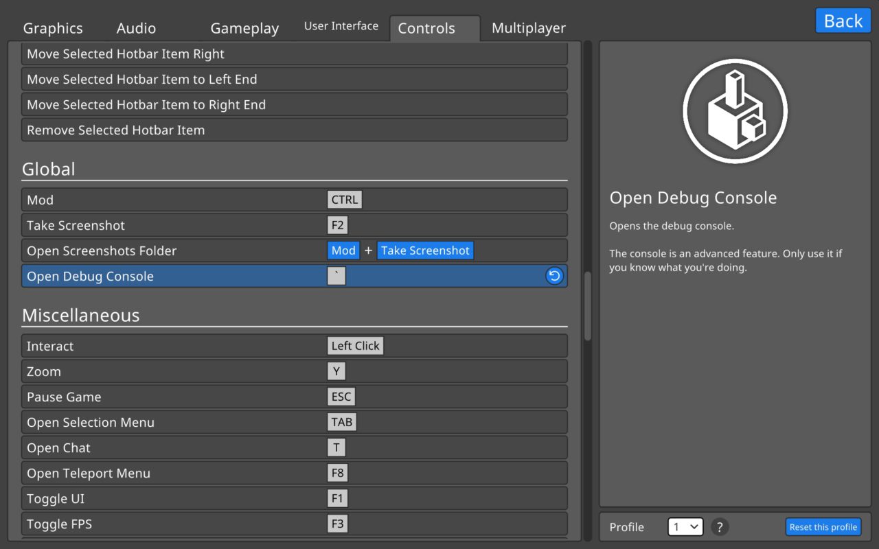
Bring up the debug console
- Press the [`] key in-game – or whatever key you have defined for “Open Debug Console” in the Controls setting.
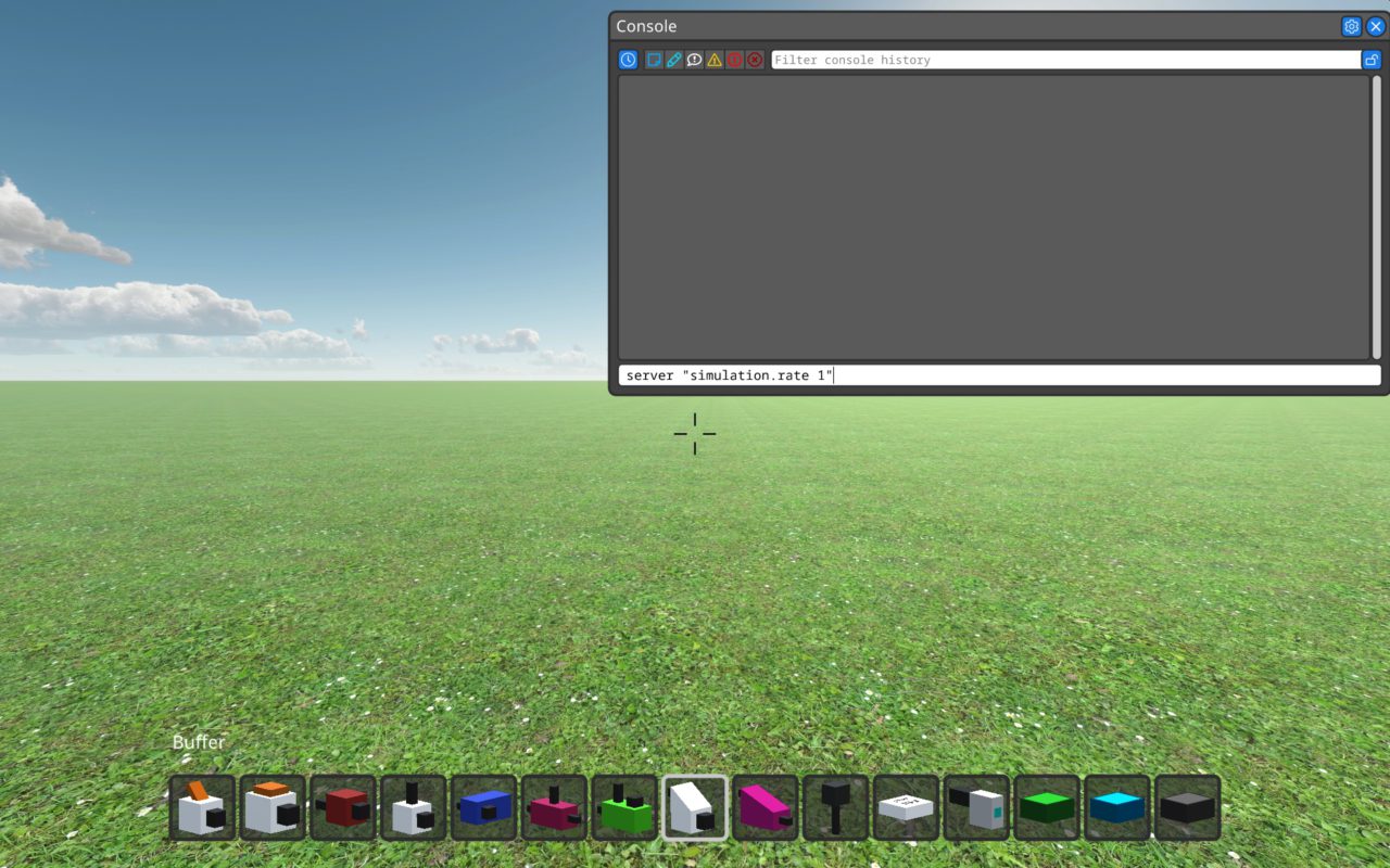
Enter the command to change simulation speed
- Enter the command server “simulation.rate X” waar X is an integer value, specifying how many ticks per second should be computed.
Signal Propagation
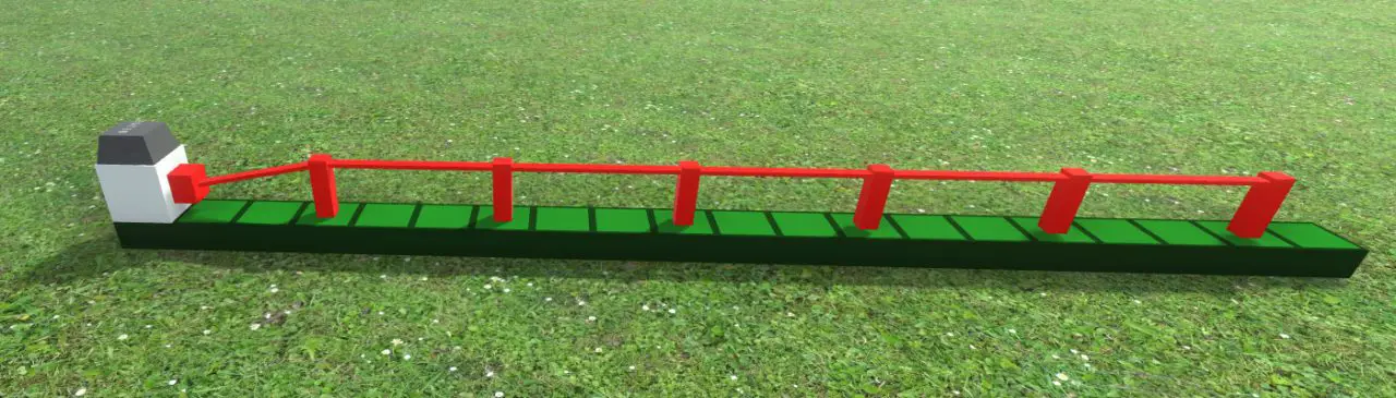
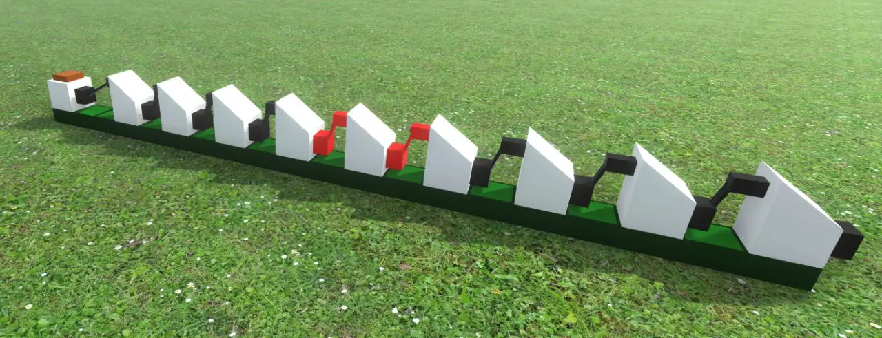
Als gevolg hiervan, signals are being transmitted throughout your system. This propagation can be easily observed by setting the simulation speed to one or a small number of ticks per second. Although connections between pegs are instantaneous, most elements require one tick to convert an input signal to an output signal. The buffer is an element with a single input and a single output. It takes one tick to transfer, and chaining them in a row is a nice way to visualize signal propagation along the chain.
We can connect such chains in a circular manner and ‘insert’ a TRUE signal at any time and point:
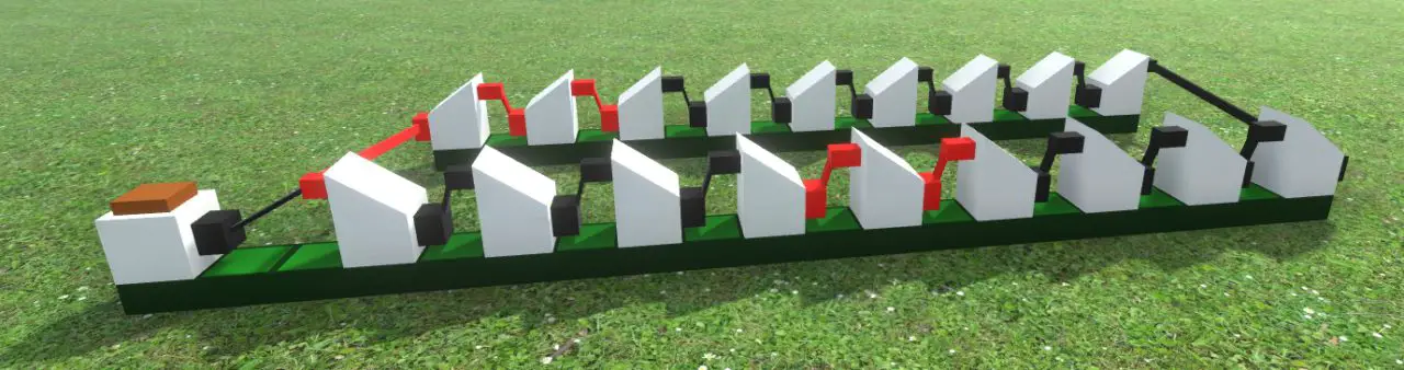
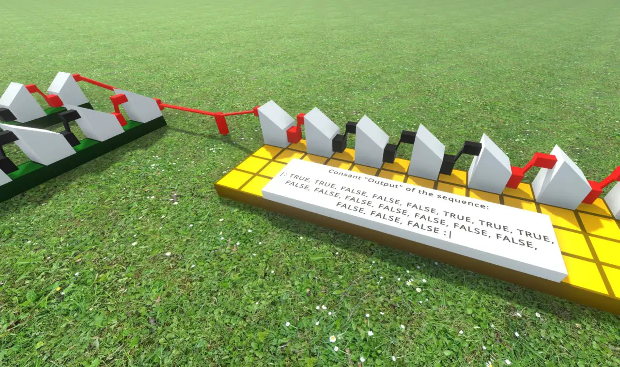
Because signals do not expire, this will result in an infinite loop, and the timing of those signals will be saved. Because any peg can have multiple outgoing connections without affecting the signal, such loops can be used to ‘generate’ any repeated sequence of TRUE and FALSE signals:
Signal insertion could be accomplished with any of the switches, knoppen, or keys; Echter, the duration for which they set a signal TRUE is dependent on how long the control is activated. A single-tick signal will not be received unless it is correctly timed.
This isn’t a problem at a simulation speed of one tick per second, but it becomes more difficult at higher speeds.
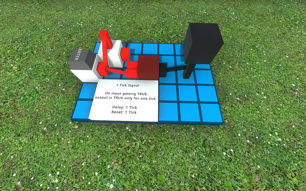
One-Tick Trigger
With a tiny bit of logic, one can convert a long-duration signal into a single-tick impulse. The following simple circuit achieves this:
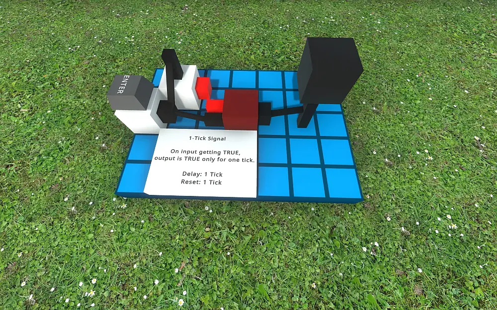
The above depicts the ready-state of the circuit.
Setting the input to TRUE will pass with 1 tick delay:
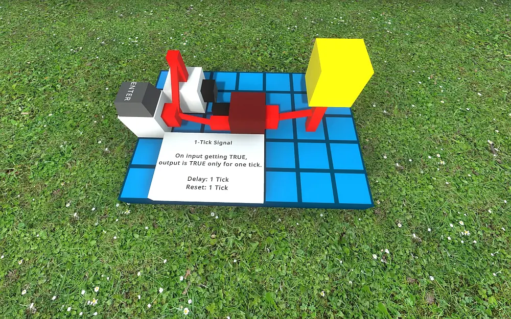
But the next tick will no longer pass a TRUE signal.
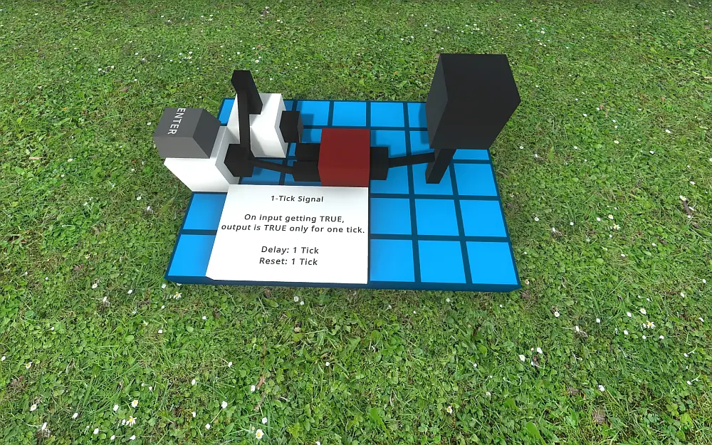
This locked state remains as long as the input is TRUE. Once it becomes FALSE the system requires one more tikken before returning to the ready-state of the beginning:

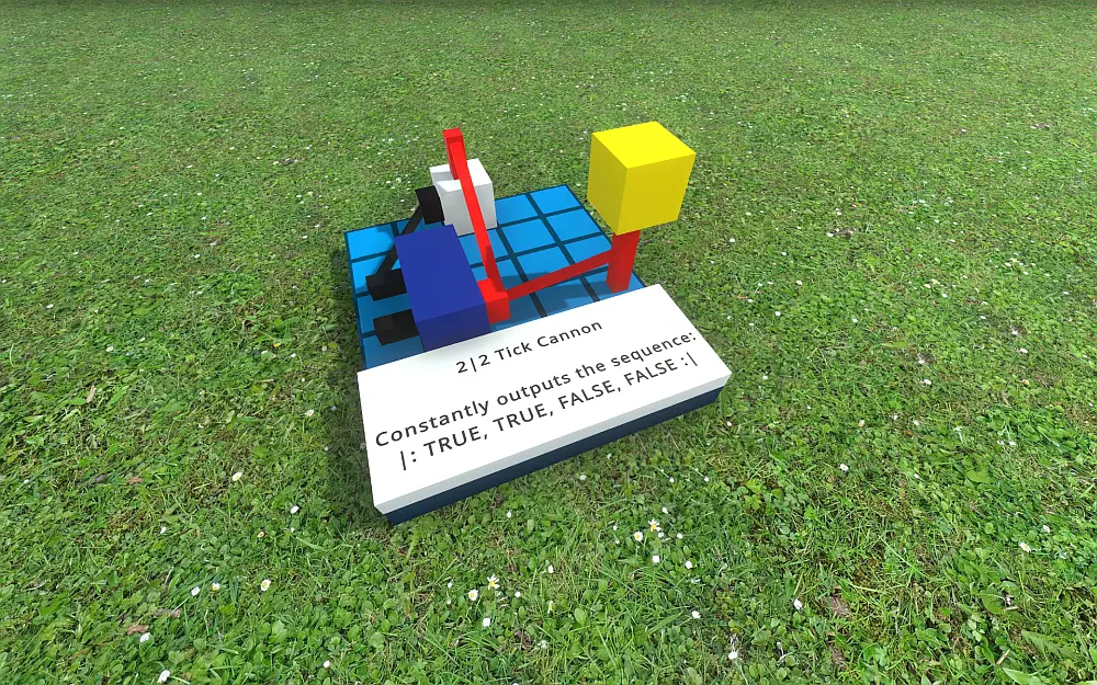
Some Simple Tick Canons
A circular chain of programmed buffers can be used to produce a constant stream of arbitrary signal configurations as shown previously, but there are also some simpler – and more compact – builds that achieve regular signal patterns.
There are certainly many different ways to build such canons, and finding them is part of the fun of LogicWorld, but to get you started: Hier zijn enkele voorbeelden:
De 2 : 2 Tick Canon
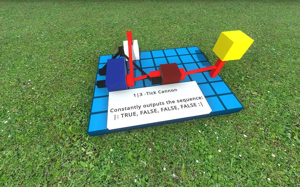
De 1 : 3 Tick Canon
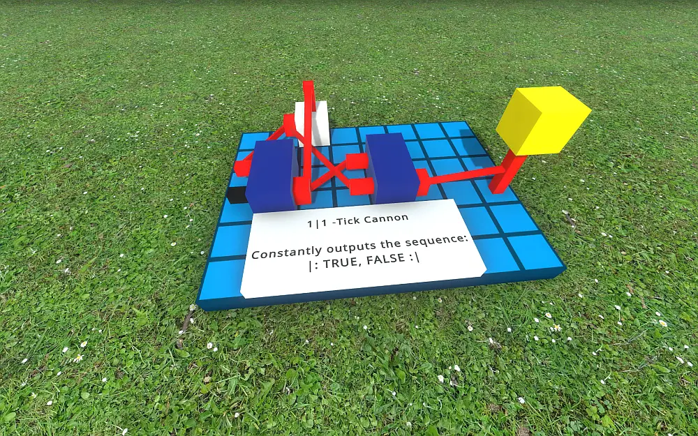
De 1 : 1 Tick Canon
Dat is alles wat we vandaag hiervoor delen Logic World gids. Deze handleiding is oorspronkelijk gemaakt en geschreven door bejoscha. Voor het geval we er niet in slagen deze handleiding bij te werken, U kunt de laatste update vinden door dit te volgen link.