
- Título: Warp Factory
- Data de lançamento:
- Desenvolvedor:
- Editor:
Information about Warp Factory is still incomplete. Por favor, ajude-nos a preencher os detalhes do jogo usando este formulário de contato.
Introduction to building Logic Gates using wires. It also delves deeper and explains how to make gates without any delay.
Introdução
Once you reach the levels with sensors and wires, you will quickly face challenges where multiple sensors need to control the same magnet/piston/portal in unison. Some of the possible configurations are trivial. Por exemplo, activating a piston when any sensor is active or releasing a magnet when two sensors are both active.
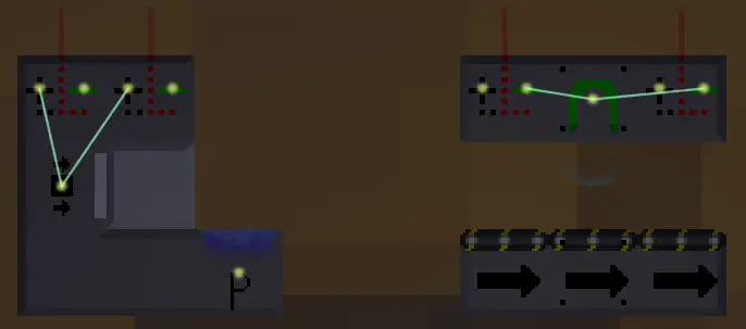
Any sensor will activate the piston (à esquerda). All sensors need to be active to release the magnet (à direita). No entanto, if we want to activate a piston when all sensors are active or release a magnet when any sensor is active, we have to make something a little bit more advanced.
Simple Piston Gates
We can use pistons to make simple logic gates. Using this approach will have some cons, but they are fairly easy to understand, so we’ll start with them.
If we want to activate a piston when two (ou mais) sensors are active at the same time, we can use an extra sensor and an extra piston. To simplify referring to them, let’s call our initial sensors our input sensors and our initial piston for our output piston, while we call our extra components our gate sensor e gate piston respectivamente.
We can easily make our gate piston activate when any input sensor is active (in the same way we did in the Introduction). No entanto, by instead using the negative side of the input sensors, it will activate if any input sensor is não ativo. Lembrar, what we want to check is if all input sensors are active, but we can rephrase that as wanting to check if no input sensors are “not active”. When that is the case, our gate piston will not be active. By using our gate sensor, we can detect the state of the gate piston and then control the output piston accordingly.
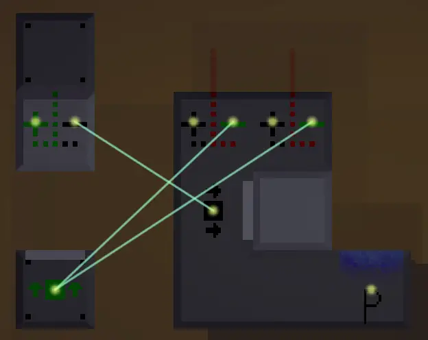
By using an extra sensor and piston, we can create an AND-gate. Loose pieces are colored white. (The reason the piston isn’t extended is simply that we haven’t started the factory.)
In a very similar way, we can make a magnet release if at least one sensor is active. Note that we here use the positive side of our input sensors, while still using the negative side of our gate sensor.
An extra sensor and piston can also become a NOT-gate that we attach to the trivial OR-gate (the OR-gate is just connecting multiple positive sensor wires to the same block).
How you build the gate sensor and gate piston in relation to each other can be done in many different ways. In the image below, you can see some of the possible variants.
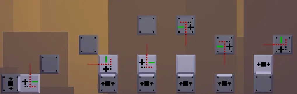
Variants of the piston gate. Loose pieces are colored white.
Chaining Gates
In the previous section, we built an AND-gate and a NOT-gate. By using the positive output of the gate sensor in the AND-gate, we get a NAND-gate (NOT AND) and by using multiple input sensors (like we did) for the NOT-gate, we get a NOR-gate (NOT OR). In computer science, you can famously build all boolean (verdadeiro/falso, one/zero, high signal/low signal) logic by using just NAND-gates or by using just NOR-gates. That means that we can build whatever logic we want with a simple piston gate design. We might need multiple piston gates, but we can do it.
Como exemplo, let’s try to build an XOR-gate (EXCLUSIVE OR). An XOR-gate should output a signal if any one input is active, but not if both the inputs are active. Para fazer isso, we can check whether at least one input is active and if both are not, ou, em outras palavras, an AND-gate with inputs from an OR-gate and a NAND-gate. No entanto, since our AND-gate design uses inverted inputs, what we actually need is for our AND-gate to get its inputs from a NOR-gate and an AND-gate.
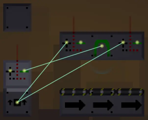
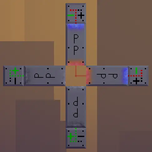
An XOR-gate. The left-most gate is the NOR-gate. The AND-gate for the input is on the right. The middle one is the AND-gate that uses the other gates’ outputs as its inputs.
Piston Delays
Pistons will take a single tick to extract or retract their arms. A single tick is not a long time, but sometimes timing is crucial for a factory to operate properly and efficiently. As we saw in the previous section, simple gates can be chained together to form more complex logic. The combined logic of multiple gates will take a number of ticks equal to the longest chain of gates. Por exemplo, the XOR-gate from the previous example will take 2 ticks to update.
Ele contém 3 basic gates, mas 2 of them can operate at the same time. Not only will the delay increase with complexity, but the final output may also flicker between unstable values and the actual values. This can happen if there are sub-chains in the logic of different lengths, as that means one sub-chain changes before the other. As long as there’s a delay at our gates, we will have to consider delayed and unstable outputs that may or may not cause problems in our factories. In computers, logic gates have tiny delays as well, so a clock is used to compensate.
The output values are only used when the clock pulses, resulting in an unstable behavior being ignored (as it happens between clock pulses). While we could create some sort of clock ourselves, we have access to something computers don’t: Portais.
Instant Gates
By using portals, we can create logic gates with a 0-tick delay. This will make all the concerns from the previous section completely irrelevant. The portal gates can be slightly harder to understand than the piston ones, so it might be good to use piston gates, para começar. The core concept of the portal gate is the fact that sensors can see through a portal, detecting what’s on the other side.

The sensors view the world through a series of portals. Note the red sensor line.
We will never detect anything on the other side, no entanto. Esse é o ponto principal. If the sensor line reaches the other side, the sensor’s negative side will activate. We can stop the line from reaching the other side by simply turning off the portal. When the portal is inactive, the line can’t go through it and the sensor will instead see the portal block itself, making the positive side activate it.
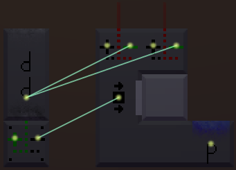
An AND-gate is made of a set of portals. Once both sensors activate, the portal will reactivate and the gate sensor will no longer see anything.
Chaining Instant Gates
To create more complex logic with portal gates, we can just chain them together, as we did with the piston gates. The difference, Contudo, is that the portal version has no delay at all.
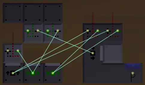
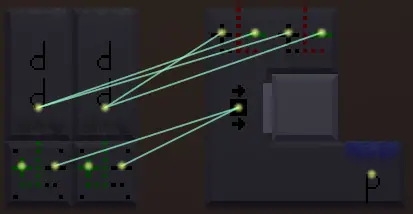
An XOR-gate is made of portals. It has a delay of 0 ticks.
No entanto, portal gates can be chained in another way as well. We can give each gate sensor multiple sets of portals. Dessa forma, the sensor’s negative side will only activate if all portal pairs are open.
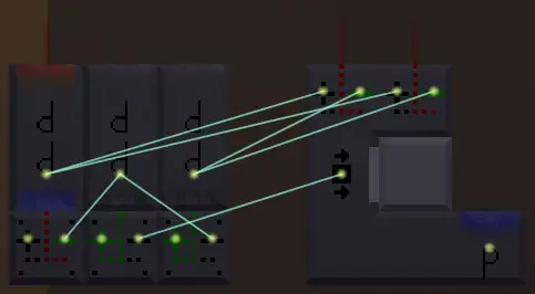
Another XOR-gate. This one only has two parts, one checking if the first input is the only active one, the other one checking if the second input is the only active one.
Na maioria das vezes, we don’t actually need to use multiple sets of portals, as the input signals can all go to the same one. No entanto, using multiple pairs of portals can make it easier to see what’s going on as it’s easier to see what portal is preventing the sensor line from going through.
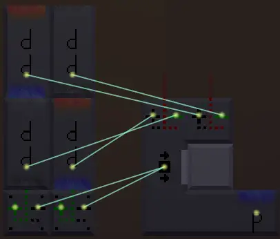
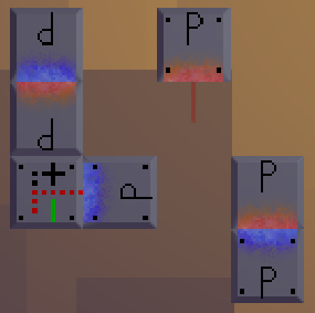
A more compact version of the XOR-gate.
Compact Factories
A property that the portal gates have is that they are really flexible when it comes to how and where you build them. I personally like to clean up my factories once they work and pack their parts together fairly compact (how much I bother to do this varies from level to level). When building a portal gate, the only thing that’s important is that the sensor can see an empty spot when all the portals are open.
4 portal gates each facing the same empty spot.
 One portal gate with 3 portal pairs.
It should go without saying that the weirder you build them, the harder it’s going to be to keep track of what they do.
Real Puzzle Example
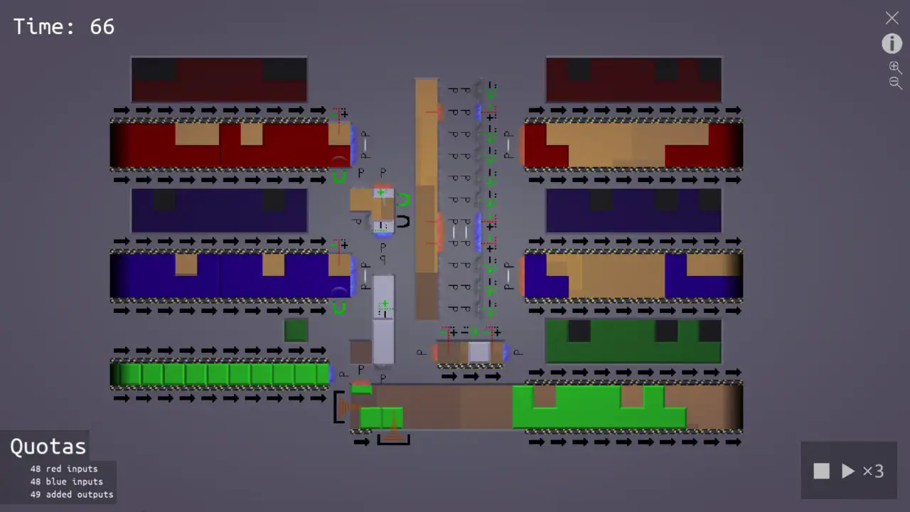
This is a solution to the level of “Adder” no “Digitalia” group. The red and blue blocks’ 8 bits should be added together and outputted with a green block. By using a bunch of portal gates, I’m able to produce a new 8-bit output every 24th tick (3 ticks per bit).
Isso é tudo o que estamos compartilhando hoje para isso Warp Factory guia. Este guia foi originalmente criado e escrito por Swen V. Caso não atualizemos este guia, você pode encontrar a atualização mais recente seguindo este link.