- Título: Occupy Mars: O jogo
- Data de lançamento:
- Desenvolvedor:
- Editor:
Information about Occupy Mars: O jogo ainda está incompleto. Por favor, ajude-nos a preencher os detalhes do jogo usando este formulário de contato.
Repairing circuit boards in Occupy Mars: The Game involves a step-by-step process that can be both enjoyable and challenging. Enquanto joga o jogo, I realized that there wasn’t a guide available, so I decided to share my knowledge and experience to help others who may be new to this type of activity.
Having real-life experience in circuit board repair, as well as having played the repair minigame during the demo, closed beta, and now early access, I believe I can provide valuable tips and instructions to make the process easier for everyone. Whether you’re a beginner or have limited experience, this guide will assist you in successfully repairing circuit boards in the game.
Select Board to repair
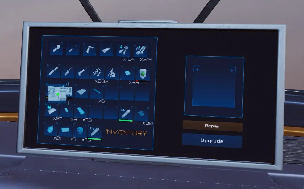
To initiate the repair process for a specific board in your inventory, simply click on it and drag it towards the square located on the right side. Once you have positioned it over the square, release the click.
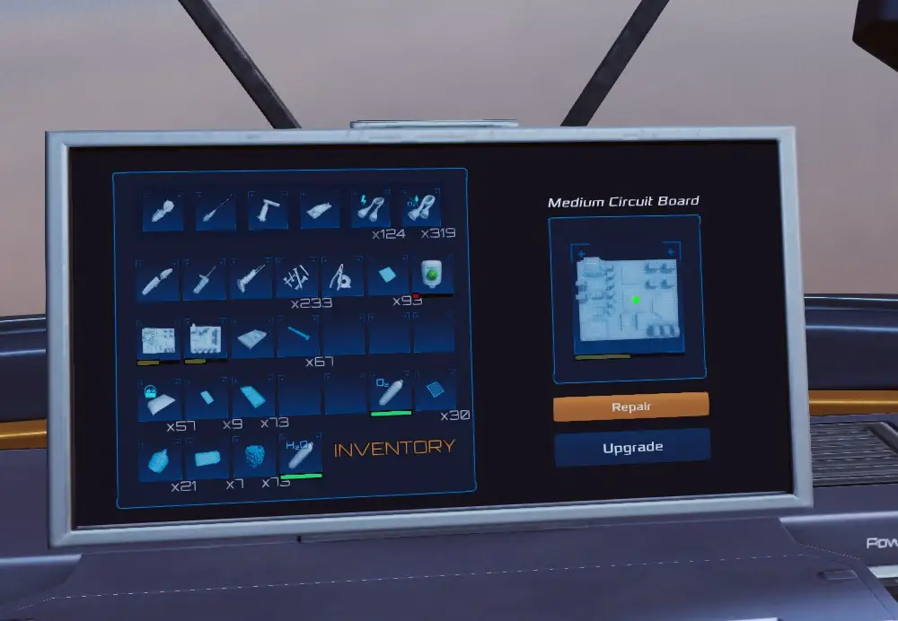
As soon as you release the board, it will appear in the square, and you will notice that the repair option becomes illuminated.
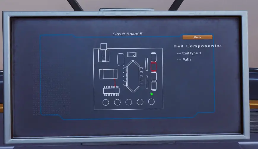
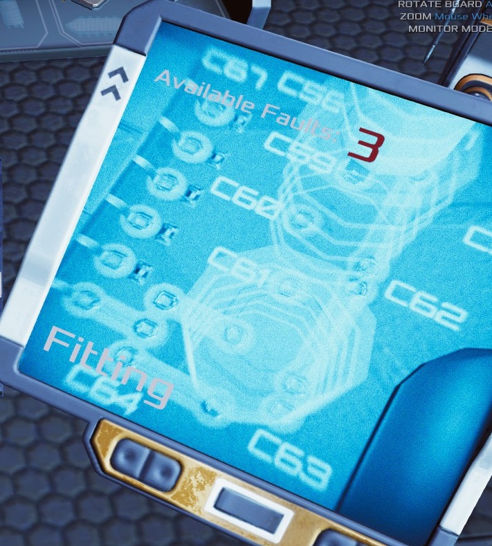
Proceed by clicking on the repair option to commence the repair procedure. This action will present you with a Diagnostic screen that displays all the issues that need to be addressed. It is worth noting that larger boards with significant damage may require additional repairs to be carried out.
Removing Broken Components
- Utilize the magnifier tool to locate red dots, which proves helpful in identifying solder points and starting points for board trace repairs.
- Prioritize the removal of any faulty components, ensuring they are not already missing. It is worth noting that there may be a bug where identical damaged components need to be completely removed for any phantom parts to be visible.
- Adjust your proximity to the board using the W and S keys. This action also affects the position of the magnifier. Remember to keep an eye out for those red dots.
- Employ the A and D keys to rotate the board when necessary. This feature may not be frequently used once you become more skilled, except for occasional trace repairs and aligning new components.
- We will be breaking this down into:
- Flip the board over using the Q key to facilitate the removal of solder (using a hot air tool) from a faulty component. Remember that flipping the board changes the orientation of the component—what was once close to you will now be farther away, and what was on the left will now be on the right.
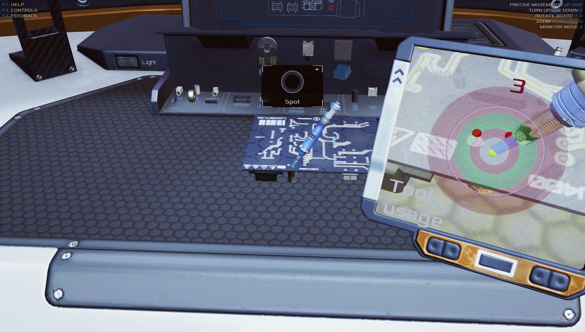
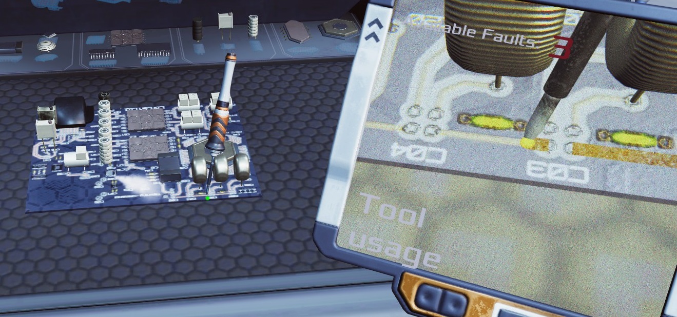
- Make sure you have the hot air tool in hand and use the magnifier to aid in locating the solder point.
- Align the tip of the tool with the red dot in the magnifier. Once properly aligned, the dot will turn green. Adicionalmente, a box labeled “SPOT” will appear above the board.
- Click and hold the left mouse button. A bullseye will appear, consisting of alternating red, verde, vermelho, and transparent sections. A white circle will begin shrinking from the outer edge towards the center. Release the mouse button once you reach the green section. The goal is to release it within the green circle.
- Repeat this process for each solder point on the component.
- Flip the board back over, left click on the component to grab it, and then right click to discard it. Repeat this step as needed.
- Once all components have been removed, open the spare parts panel located just below the monitor. Para acessá-lo, left click on the panel. The components in the panel are organized by type.
Install New Components
Phantom indications will manifest within the magnifier, indicating the specific locations where new components need to be installed.
- Locate one of the components listed in the “bad parts” section on the right side of the monitor. Left click to grab a new component from the list. On the circuit board, you will observe a light grey phantom marking where the component should be placed.
- Move the component over the phantom and align it accordingly, then left click again. The component should snap into place. It may be necessary to use the A and D keys to rotate the board for better alignment.
- Obtain the solder tool.
- We will be doing this again:
- Flip the board over using the Q key to prepare for soldering. Keep in mind that flipping the board changes its orientation—what was once close to you will now be farther away, and what was on the left will now be on the right.
- Utilize the magnifier to assist in locating the solder points.
- Align the tip of the solder tool with the red dot. Once properly aligned, the dot will turn green. A box labeled “SPOT” will also appear above the board.
- Left click and hold. A bullseye will appear, consisting of alternating red, verde, vermelho, and transparent sections. A white circle will begin shrinking from the outer edge towards the center. Release the mouse button once you reach the green section. The objective is to release it within the green circle.
- Repeat this process for each solder point on the component.
- Flip the board back over using the Q key.
- Repita as etapas 7 para 10 as necessary for additional components.
Repairing Paths
If you need to repair a path (indicated by a red line) no quadro, it is recommended to locate it at this stage. Utilize the magnifier on the top side to identify a red dot corresponding to the path.
When aligning the tip of the solder tool with the red dot, left click to activate it. The magnifier will display a green indication when the left mouse button is held.
Follow the rough texture along the path, moving the solder tool point accordingly. In case you deviate too far, simply realign the tip and continue until the path is repaired.
Once all the necessary steps are completed, the board will vanish from the table and return to your inventory as a repaired item.
Isso é tudo o que estamos compartilhando hoje para isso Occupy Mars: O jogo guia. Este guia foi originalmente criado e escrito por ObiDaddy. Caso não atualizemos este guia, você pode encontrar a atualização mais recente seguindo este link.