
A simple surge protector can protect your junction boxes by charging your batteries in Barotrauma.
작동 방식
The circuit determines the difference between the output and the load and adjusts the battery charge rate to prevent overvoltage.
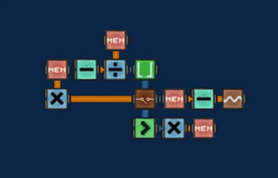
The circuit consists of three main parts: the top, 가운데, and bottom. The top part calculates the battery charge rate. The middle part gradually reduces the charge rate to 0% at a consistent pace. The bottom part activates the circuit when overvoltage occurs.
The Charge Rate Calculator
For this part you will need:
- Subtract Component
- Divide Component
- Memory Component
- Floor Component
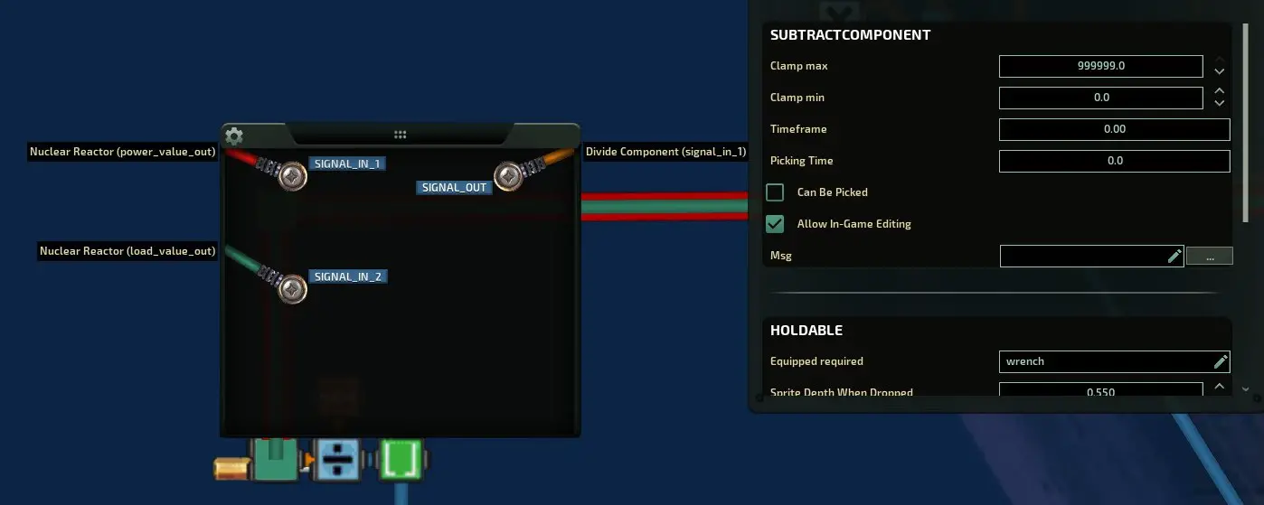
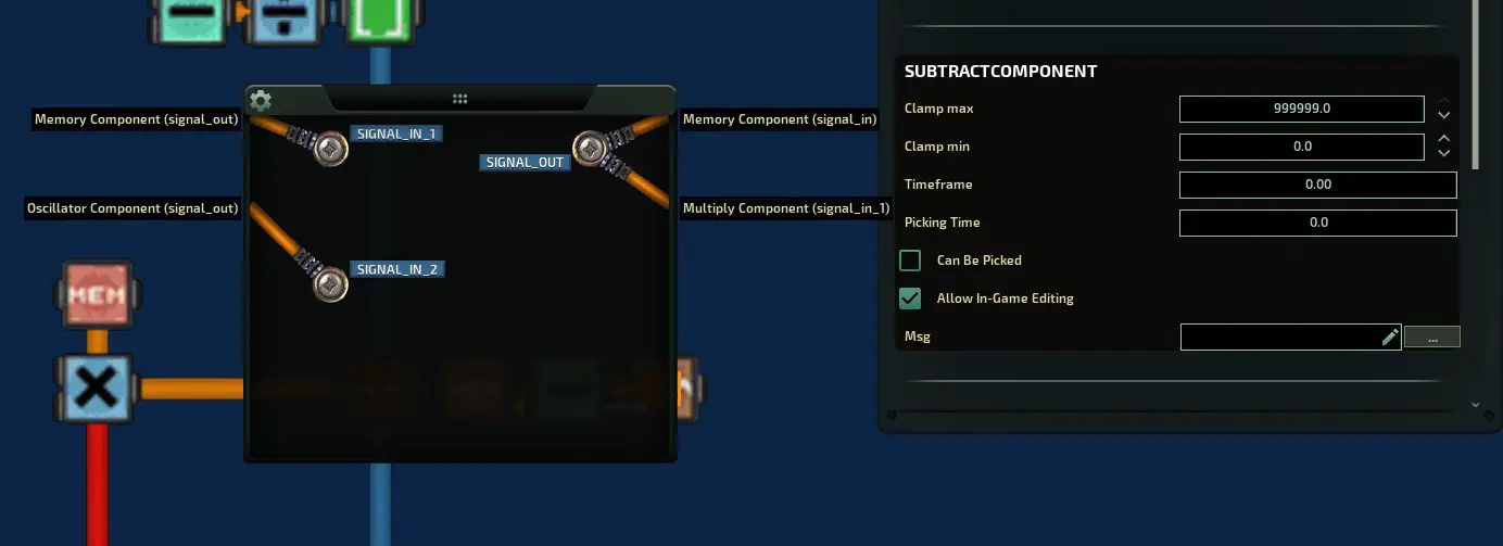
Start by using the subtract component and connect the POWER_VALUE_OUT of your reactor to SIGNAL_IN_1 and the LOAD_VALUE_OUT to SIGNAL_IN_2. 그 다음에, set the Clamp min value to 0.
다음, connect the SIGNAL_OUT to the SIGNAL_IN_1 of the divide component.
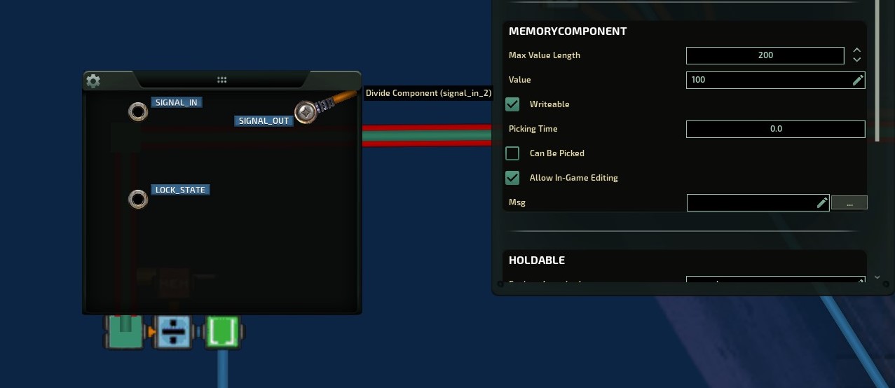
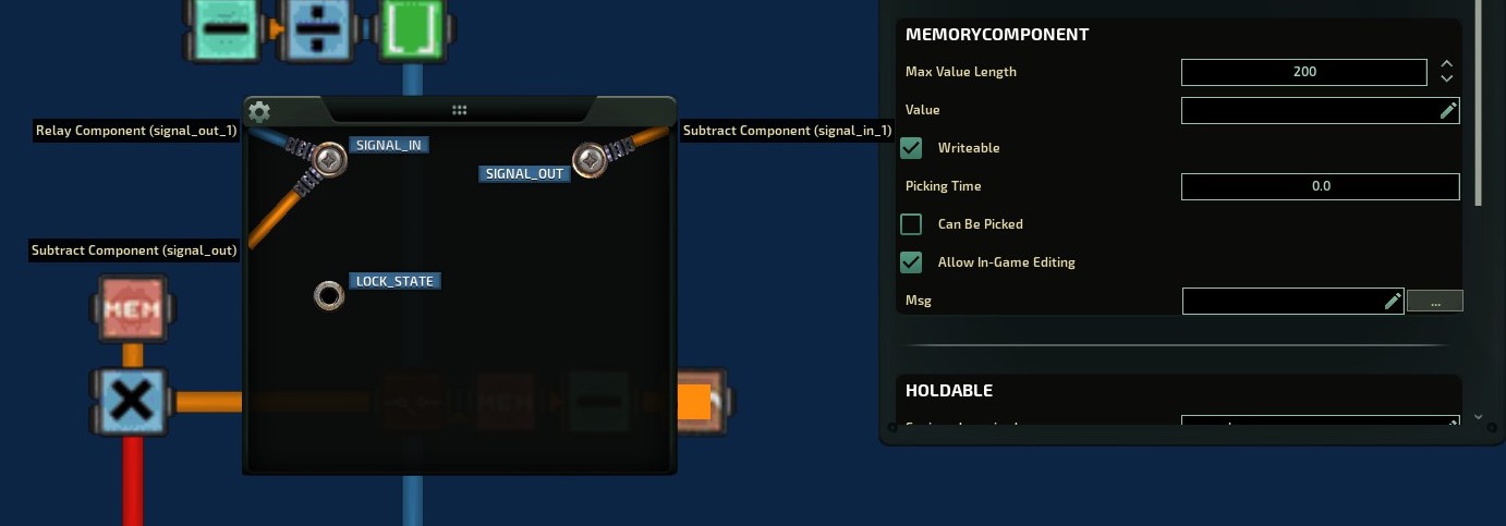
Setup your memory component with the value being 10% of your batteries combined charging power (So if you have two batteries with 500kW max recharge speed each that would be 50 + 50 = 100kW).
Wire the SIGNAL_OUT of the memory component to the SIGNAL_IN_2 of the divide component.
Set the divide component Clamp max to 11 and the Clamp min to 0. Wire its SIGNAL_OUT to the floor component.
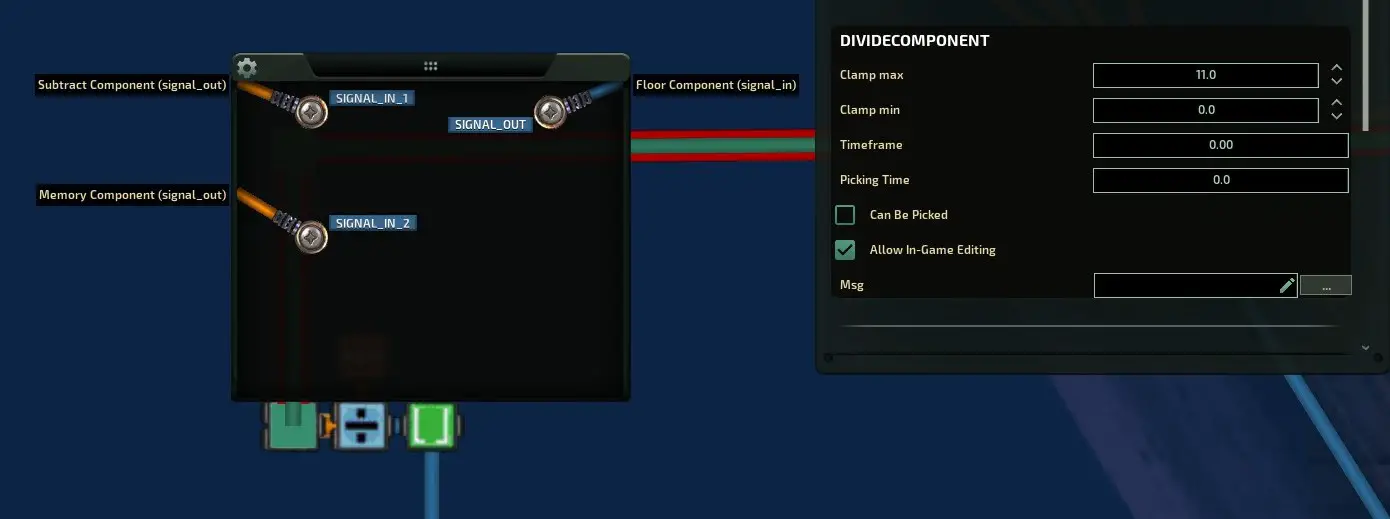
This completes the calculator for the charge rate. We will multiply it by 10 later so it sets the charge rate properly but for now you will want this to be between 11 그리고 0.
Step Down Circuit
The aim of this circuit is to step the charge rate down from the initial value made by the calculator back down to zero. So if the calculator sends it a 10 all it does is count down to 0.
당신은 필요합니다:
- Subtract Component
- 2x Memory Component
- Multiply Component
- Oscillator Component
- 계전기
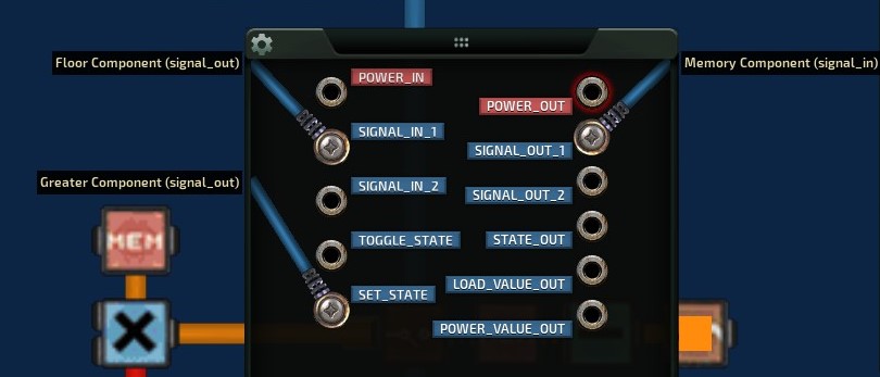
Start with the relay and wire the SIGNAL_OUT of the floor component from the calculator into SIGNAL_IN_1 of the relay. The SIGNAL_OUT_1 will go into the SIGNAL_IN of the memory component.
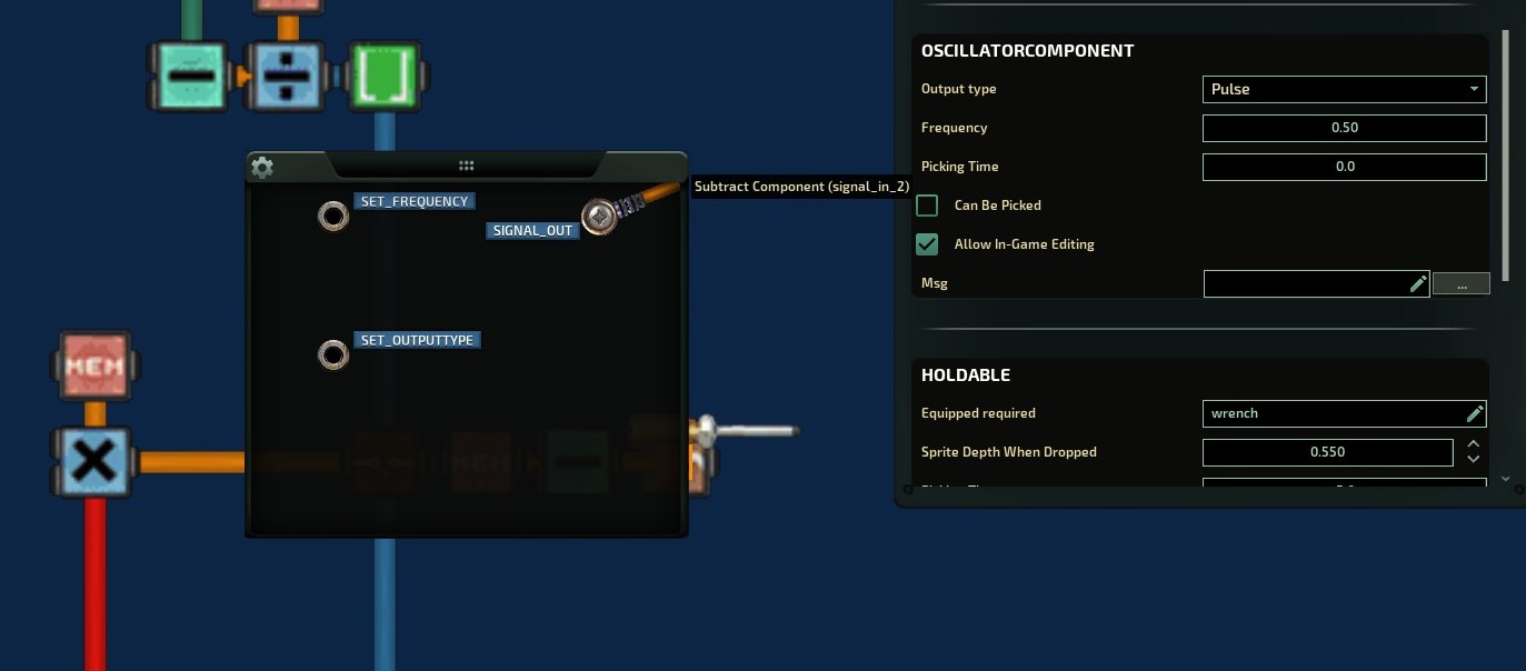
We are gonna leave that alone for now and move over to the oscillator component.
It should be an output type of Pulse with a frequency of 0.5 and wire its SIGNAL_OUT into the SIGNAL_IN_2 of the subtract component. The frequency is how fast it will change the charge rate so play around with this number to find a speed you like.
Now back to the memory component. Wire its SIGNAL_OUT into the SIGNAL_IN_1 of the subtract component. Then wire the SIGNAL_OUT of the subtract BACK into the SIGNAL_IN of the memory component. Set the Clamp min of the subtract to 0. This is going to take the initial value from the calculator and keep subtracting 1 from it.
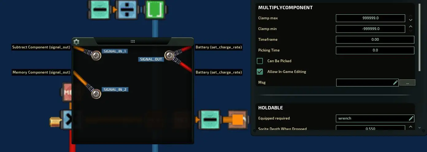
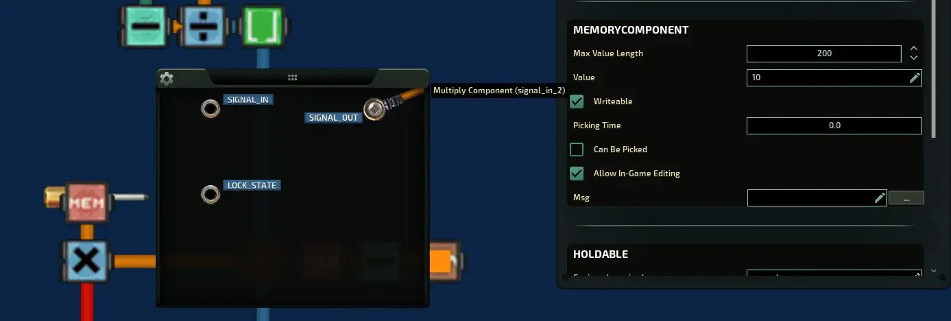
Also wire the SIGNAL_OUT of the subtract component into SIGNAL_IN_1 of the multiply component. Set your 2nd memory component to a value of 10 and wire that into the SIGNAL_IN_2. Then the SIGNAL_OUT of the multiply goes into the SET_CHARGE_RATE of your batteries.
This will turn your value back into a percentage so the charge rate is set properly.
Overvoltage Detector
The last piece of this will trip the circuit when a certain amount of overvoltage is reached.
당신은 필요합니다:
- Memory Component
- Multiply Component
- Greater Component
If you’re a keen engineer you may have noticed the charge rate calculator is constantly computing the charge rate which causes the charge rate to jump around as the load catches up to the output.
This circuit will take the charge rate value when the output is at a certain value over the load. You will want to change this value depending on the sub you are using.
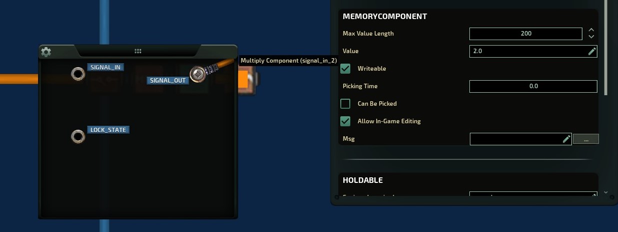
First set the value of your memory component, this value will vary! A default junction box has an Overload Voltage of 2.0 meaning the output must be 2x the load for the junction box to take damage. This value is different between the vanilla subs for example the Dugong is 1.7 while the Typhon is 1.5. Load the sub you’re using in the editor and check the Overload Voltage value. This will be the value of you memory component. In this instance I will be using the default 2.0 값.
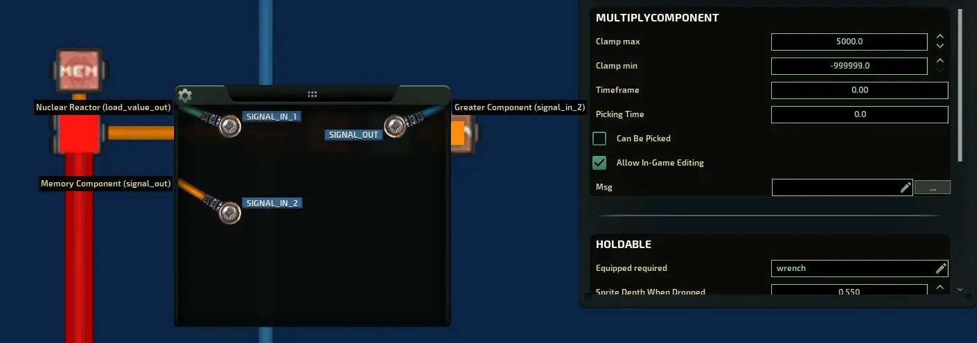
Wire the SIGNAL_OUT of the memory component to the SIGNAL_IN_2 of the multiply component. Then wire the reactor’s LOAD_VALUE_OUT into SIGNAL_IN_1. Set the multiply Clamp max to the Max Output of your reactor, in this case it is 5000kW.
Take the multiply component’s SIGNAL_OUT and wire it to the SIGNAL_IN_2 of the greater component. Then wire the POWER_VALUE_OUT to its SIGNAL_IN_1. Set the output of the greater component to 1 and its False output to 0.
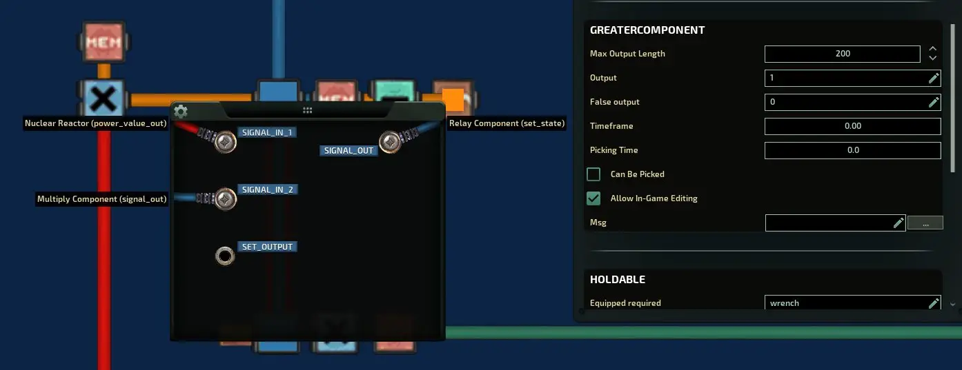
마지막으로, wire the SIGNAL_OUT of the greater to the SET_STATE of the relay from before and you’re done!
Issues and Extra Info
A couple issues with this circuit are that the batteries cannot be full for this to work properly and the circuit will not turn off once it trips. So if your captain goes from full speed to dead stop the circuit will run but if he speeds back up again the circuit will still run its course even though there is no more overvoltage to account for. You can wire up a second check for this if you like but I found it to be a non-issue.
지금, you may have noticed in the charge rate calculator the clamp max goes to 11 어느 것이 될 것인가? 110% charge rate which is impossible. The reason I set it to 11 is because of the way the oscillator component works. Since it is always pulsing, depending on the timing of when the circuit trips, it could tick right when it trips causing you to skip 100% charge rate and go straight to 90%. Starting at 11 makes it a little more consistent and you can even increase this number if you want the batteries to stay at max charge for longer.
For the frequency of the oscillator, 나는 찾았다 0.5 to be a good number since it gives plenty of time for the output to catch up if you’re running automatic control. If you want it to charge for longer tweak the number down to your liking.
On the overvoltage detector, you can set the value of the memory component to be a little less than the value defined by the junction boxes if you want it to trip the circuit a little sooner. Setting the value to 1.6 on a Dugong with an overload value of 1.7 예를 들어. Since it takes about half a second for the circuit to adjust the charge rate at the beginning you can avoid all damage this way but it should take very little damage anyways if you don’t do this.
And that’s it feel free to ask any questions or let me know if I messed up somewhere Cheers!
이것이 오늘 우리가 공유하는 모든 것입니다. 압력상해 가이드. 이 가이드는 원래 작성자가 작성하고 작성했습니다. DaBalla261. 이 가이드를 업데이트하지 못한 경우, 다음을 수행하여 최신 업데이트를 찾을 수 있습니다. 링크.