Since two-component «Bang-Bang» style reactor controllers were removed from the game with the release of the «Hoist the Sails» actualizar, this guide aims to provide a suitable alternative. This design in my limited testing has proven robust and universal enough for me to feel comfortable sharing. The guide assumes basic knowledge of component wiring.
Descripción general
Full Component List
- 5 Memory Components
- 4 Divide Components
- 2 Subtract Components
- 1 Adder Component
- 1 Multiply Component
- 18 alambres
This guide was made to supplement a YouTube video on this very subject, and this section will be edited to include the video at the time of release.
Turbine Output
Components For This Section
- 1 Divide Component
- 1 Memory Component
- 3 alambres
The Turbine Output is the easiest section of the circuit to wire, as well as the simplest part to understand. The formula used to calculate the optimal turbine output is L * 100 / METRO, where L is the current load of the circuit and M is the maximum power output of the reactor. Sin embargo, we are able to restructure the equation to reduce how many components we need to use.
We will instead frame the equation as L / (METRO / 100). Since M is not a variable that we can wire into our circuit directly, we will have to manually input the maximum power output of the reactor. As we are manually inputting M into the circuit, it makes sense to do the relatively simple division by 100 manually as well, thus reducing the component count by one.
The maximum power of the vanilla ships (a partir de la versión 0.19.14.0) can be found via the following table:
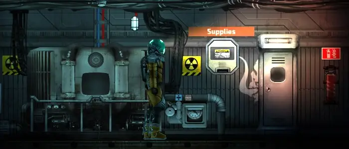
Let’s start by placing our components.
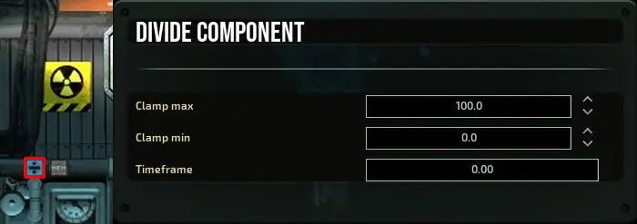
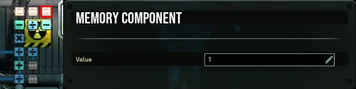
We’ll need to configure both of our components. Staring with the divide component, colocar «Clamp max» a 100 y «Clamp min» a 0.
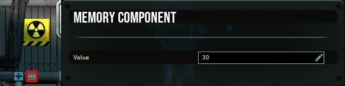
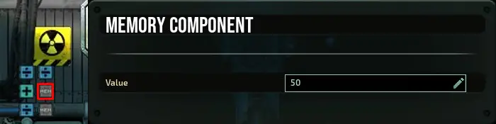
You remember the formula from above? This memory component represents our reactors maximum power output (METRO). Find the maximum power output of your reactor, either by referring to the above chart or by checking the reactor of your submarine in the submarine editor. In the case of the Dugong, the maximum power output is 3000. By dividing this value by 100, obtenemos 30.
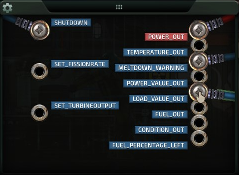
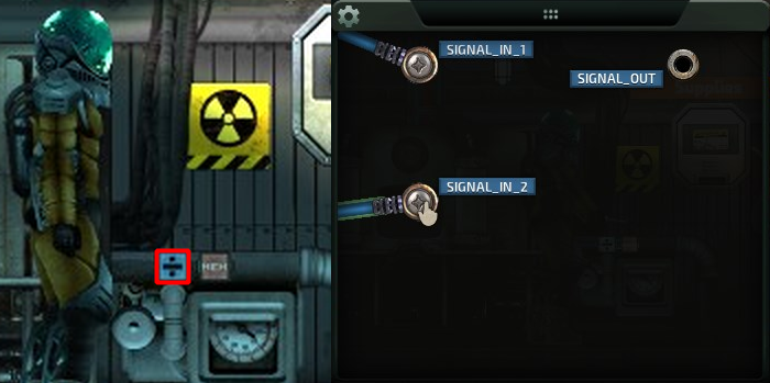
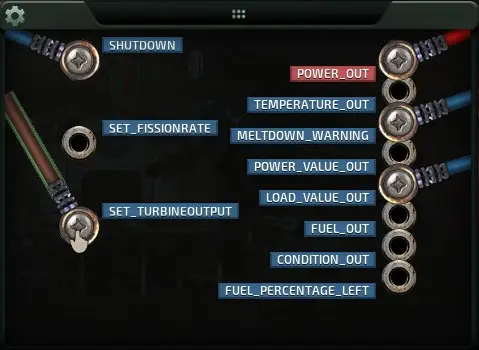
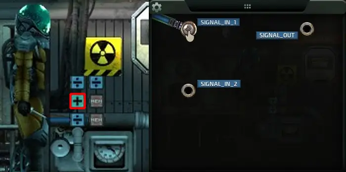
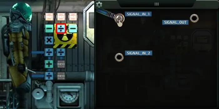
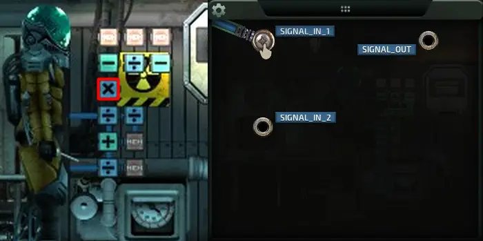
We’re now ready to start wiring. In the reactor, connect a wire to the LOAD_VALUE_OUT pin.
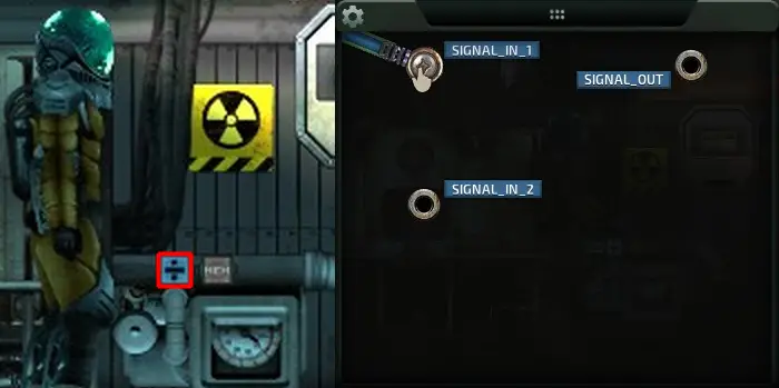
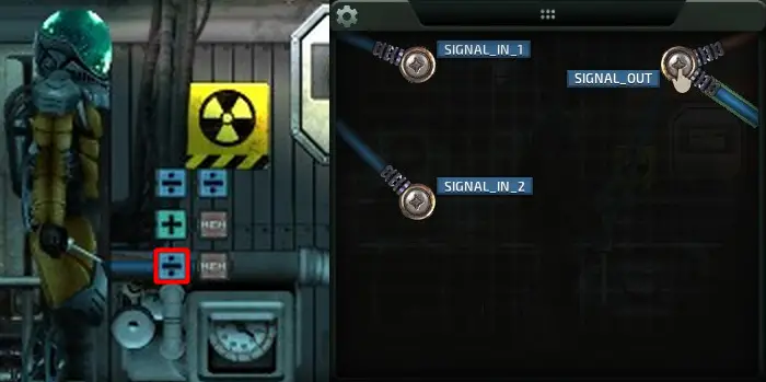
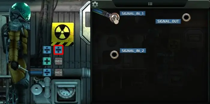
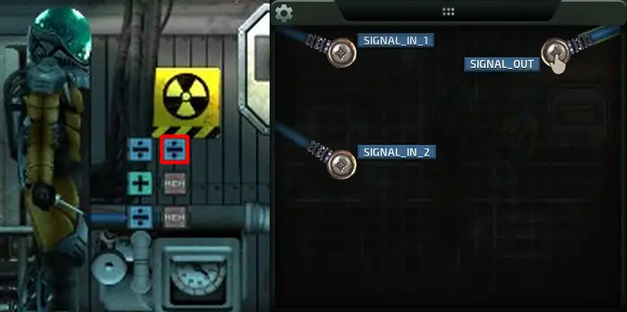
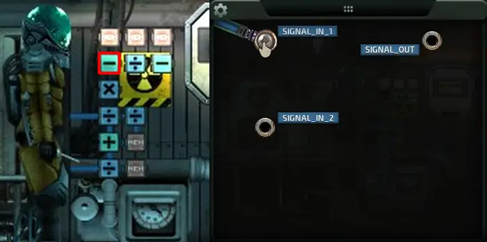
Take that wire and connect it to the SIGNAL_IN_1 pin of the divide component.
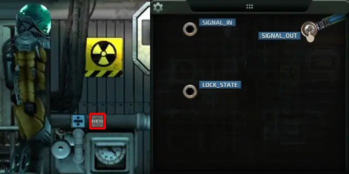
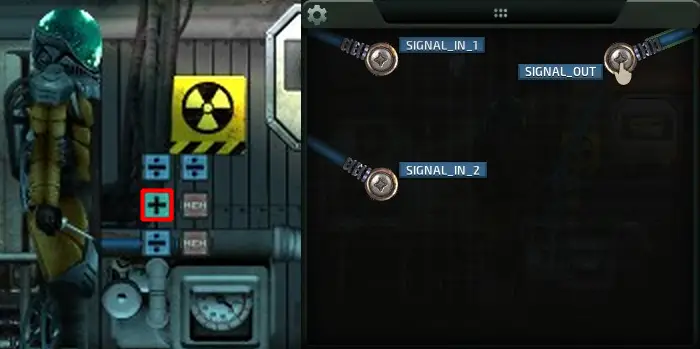
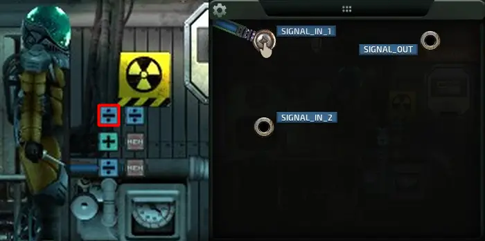
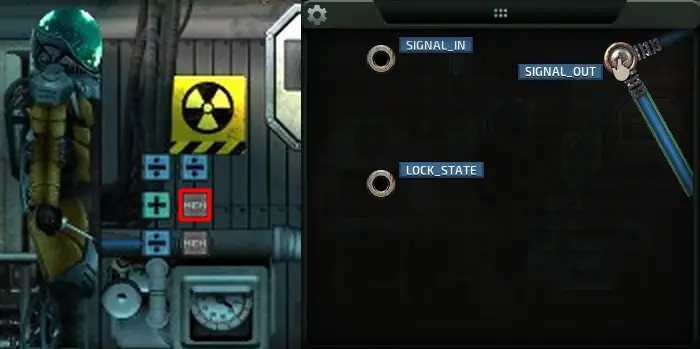
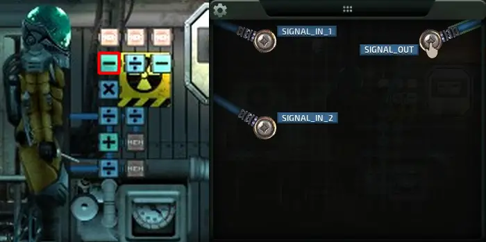
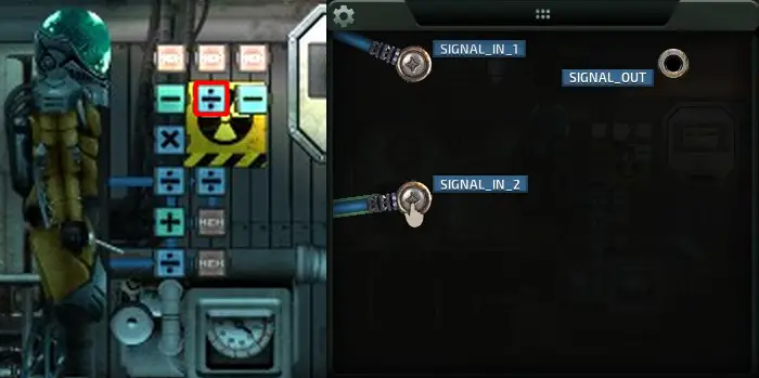
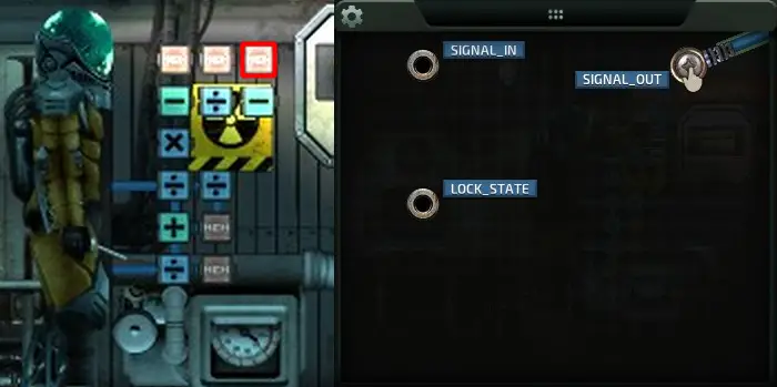
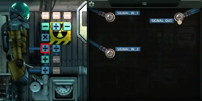
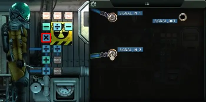
Connect a wire to the SIGNAL_OUT pin of the memory component.
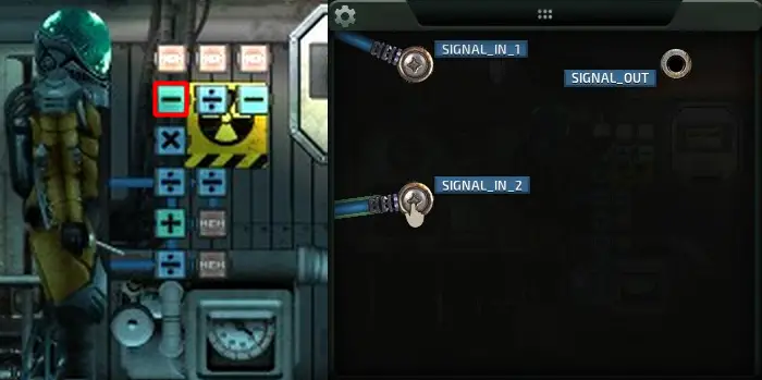
That wire connects to SIGNAL_IN_2 of the divide component.
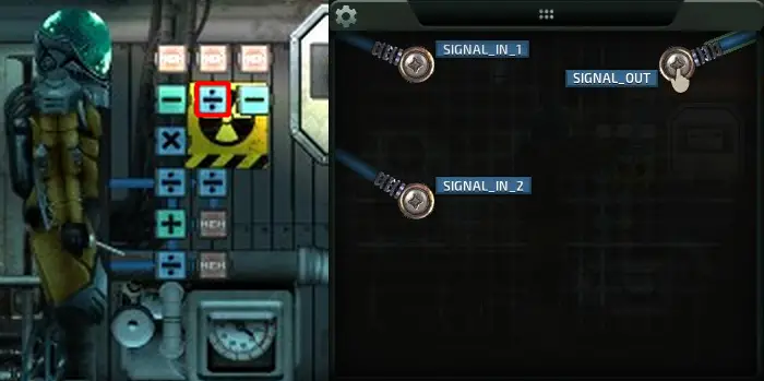
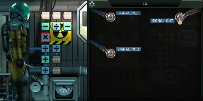
The SIGNAL_OUT pin of the divide component…
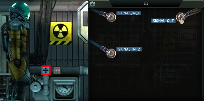
… connects to the SET_TURBINEOUTPUT pin in the reactor.
Fusion Reaction
Components For This Section
- 2 Divide Components
- 1 Memory Component
- 1 Adder Component
- 6 alambres
This section of the circuit is design to calculate the correct value the fusion reaction must be set to satisfy a given power load. The circuit takes in the Turbine Output calculated from the previous section, as well as the fuel heat potential (labelled as FUEL_OUT) as variables. It then uses these variables to calculate the ideal Fusion Reaction value.
Primero, we’ll lay down the components. I lay them out in this configuration since the Turbine Output at the bottom will feed into the Adder above it, and the left most Divide component will be the eventual endpoint for this section.

Only one component to configure for this section, which is the memory component. Set the value to 50.
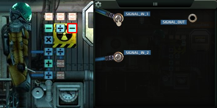
Onto the wiring, grab the SIGNAL_OUT signal from the previous section…
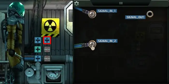
…and plug that into SIGNAL_IN_1 of the adder component.
The SIGNAL_OUT of the memory component…

… feeds into the adder components SIGNAL_IN_2 pin.

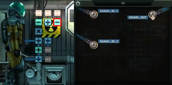
The SIGNAL_OUT pin from the adder…
… connects to the SIGNAL_IN_1 pin of the left-most divide component.
Switching gears, let’s grab the FUEL_OUT value from the reactor…
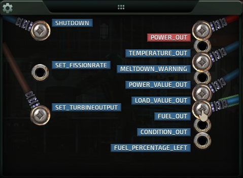
… and plug it into the SIGNAL_IN_1 pin of the right most divide component.
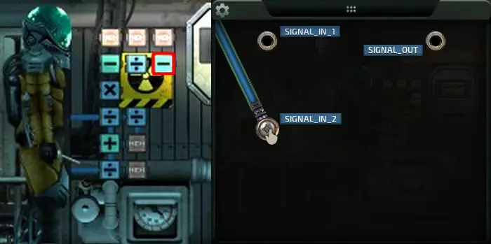
We’ll take the SIGNAL_OUT signal from the memory component again…
… and plug it into SIGNAL_IN_2 of the right most divide component.
Finalmente, we’ll take SIGNAL_OUT from the right most divide component…
… and connect it to the SIGNAL_IN_2 pin of the left most divide component.

Temperature Regulator
Components For This Section
- 3 Memory Components
- 2 Subtract Components
- 1 Divide Component
- 1 Multiply Component
- 9 alambres
We’re about half way done, and this next section is a bit of a doozy. This circuit is designed to prevent overheat conditions when the turbine output and fusion reaction aren’t quite in sync with the circuit. Por ejemplo, when ramping up from a cold start, it’s possible for the reactor to overheat and melt down. This circuit regulates the temperature; If it detects the temperature of the reactor is getting too hot, it will ramp the fusion reaction down proportionally. This ramping effect ensures that the reactor powers up quickly and efficiently, while preventing any power oscillations that could occur from circuit feedback.
Let’s place the last of our components.

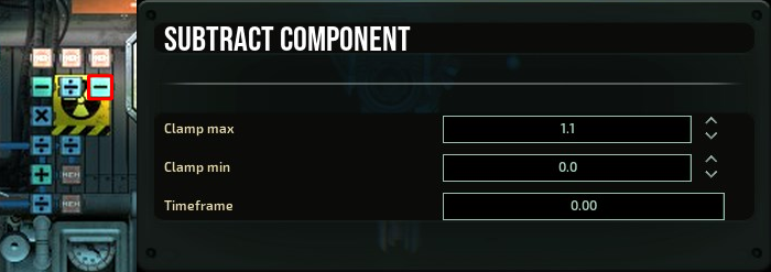
We have a bit to configure this time, so let’s start with the right most subtract component. Colocar «Clamp max» a 1.1, y «Clamp min» a 0.
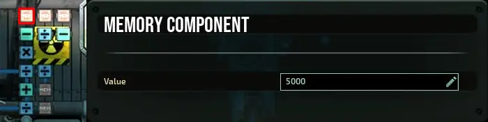
Now we can set the memory component values. De izquierda a derecha, set the Value of the memory components to 5000…
… 1000…
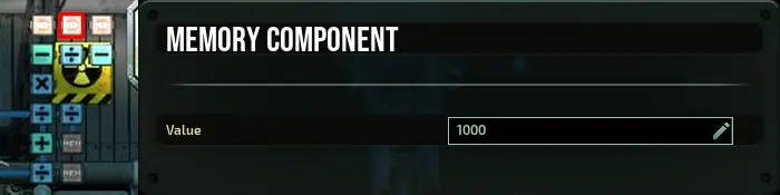
… y 1, respectivamente.
For wiring, let’s take the TEMPERATURE_OUT value from the reactor…
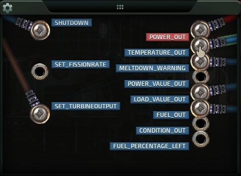
… and put it in the SIGNAL_IN_1 pin of the left most subtract component.
The SIGNAL_OUT value of the above memory component…

… goes into SIGNAL_IN_2.
SIGNAL_OUT of the left most subtract component…
… goes into SIGNAL_IN_1 of the divide component.
The SIGNAL_OUT value of the above memory component…

… goes into SIGNAL_IN_2.
SIGNAL_OUT then plugs into…
SIGNAL_IN_2 of the right most subtract component.
The SIGNAL_OUT value of the above memory component…
… plugs into SIGNAL_IN_1.
SIGNAL_OUT then plugs into…
… the SIGNAL_IN_1 pin of the multiply component.
You remember the divide component we left on in the last section? Finally we can connect SIGNAL_OUT from there…
… with the SIGNAL_IN_2 pin of the multiply component.
Finalmente, the SIGNAL_OUT of the multiply component…
… can be connected to the SET_FISSIONRATE pin on the reactor.

Conclusión
Espero que esto ayude, perhaps cleared a few things up. If you have any questions or comments, feel free to post them. I can’t promise a speedy response or even a satisfying answer, but I’ll try my best.
Eso es todo lo que estamos compartiendo hoy para este barotrauma guía. Esta guía fue originalmente creada y escrita por DrFreenote. En caso de que no actualicemos esta guía, puede encontrar la última actualización siguiendo este enlace.